Calibration for type sw style load sensors – Nexen TA100 964400 User Manual
Page 11
7
FORM NO. L-20292-C-0700
NOTE
If using one Type SW Tension Sensor, Terminals 5
and 6 must be jumpered together.
1.
Set the Power Switch to ON.
2.
Make sure the web has been removed and no other
objects are sitting or resting on the sensor roll.
3.
Rotate both S1 and S2 counterclockwise to minimum
(See Figure 15).
4.
Connect a voltmeter to TP7 (COM) and TP1 (See Figure 15).
5.
Rotate Z1 to read 0.00VDC at TP1 (See Figure 15).
NOTE
If two Type SW Tension Sensors are used, proceed
with Steps 6 and 7.
6.
Connect a voltmeter to TP7 (COM) and TP2 (See
Figure 15).
7.
Rotate Z2 to read 0.00VDC at TP2 (See Figure 15).
CALIBRATION FOR TYPE SW STYLE LOAD SENSORS
NOTE
Prior to calibration, make sure jumpers J3 and J4 are set to the No. 4 position for TYPE SW Sensors.
ZERO ADJUSTMENT (WITH ONE OR TWO TYPE SW TENSION SENSORS)
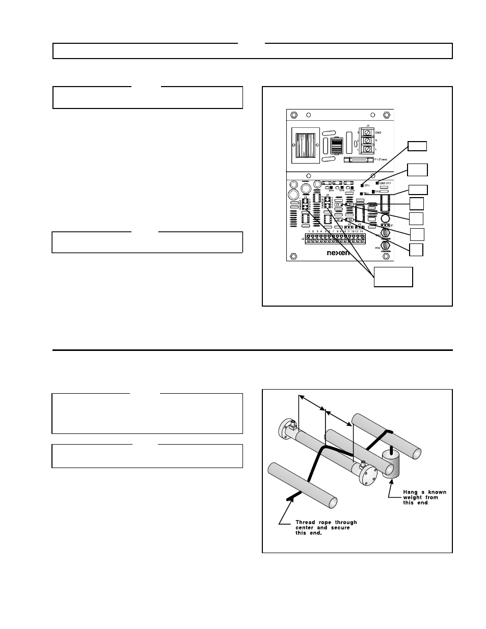
FIGURE 15
Jumpers
J3 and J4
TP7
TP2
TP1
Z2
Z1
S1
S2
SPAN ADJUSTMENT (WITH ONE OR TWO TYPE SW TENSION SENSORS)
FIGURE 16
NOTE
Before making any Span adjustments, the output
voltage level needs to represent the tension levels
required. The maximum tension level needs to be
calculated (Example: Maximum Tension = 100 Lbs.).
NOTE
When using one Type SW Tension Sensor, Terminals
5 and 6 must be jumpered together.
1.
Thread a rope or narrow web over the Sensor Roll in
the normal path. Be sure the rope or web is at the
center of the Sensor roll; then, hang a known weight
(within the range of the system) on one end of the
rope or web (Example: Maximum Tension = 100 Lbs.,
hang a 50 Lb. weight) (See Figure 16).