Nexen TCC-10 835141 User Manual
Page 6
3
FORM NO. L-20069-E-0210
STRAIGHT BORE ROTOR HUB ASSEMBLY
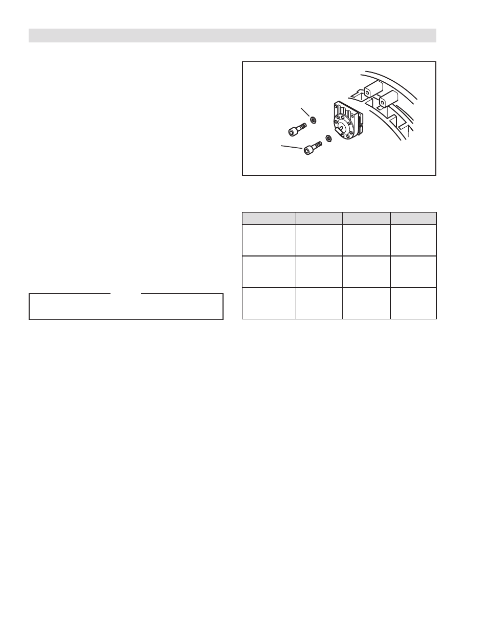
FIGURE 6
Please verify that you are in the correct rotor section for
your model. This is the Straight Bore Rotor Hub instruction
section. The instructions for the Taper Bore Rotor Hub are
in the following section.
REFER TO FIGURE 6.
1. Slide the Housing Assembly on to the shaft and
tighten the Set Screw (Item 26) to the torque
recommended in Table 1.
2. Align the Key (Item 6) with the Hub keyway and slide
the Hub and Rotor assembly (Items 1-5) onto the
shaft. Insert the Key (Item 6) into the keyway.
4. Tighten the Set Screw (Item 7) on the Hub (Item 1)
to the recommended torque (See Table 1).
5. Use the Cap Screws (Item 18) and the Lock
Washers (Item 19) to fasten one-half of the Caliper
and Friction Facing assembly to the flange side
of the Housing (Item 8) at each caliper position.
Tighten the Cap Screws to 7 ft-lbs [9.5 Nm]
NOTE
Allow 1/16" [16 mm] clearance between the
friction facings and the Rotor Disc (Item 2).
TABLE 1 Tightening Torques
Description
TCC-10
TCC-14
TCC-20
Rotor Set
Screw
(Item 7)
23 ft-lbs
[30.9 Nm]
50 ft-lbs
[67.5 Nm]
166 ft-lbs
[224.0 Nm]
Housing Set
Screw
(Item 26)
23 ft-lbs
[30.9 Nm]
50 ft-lbs
[67.5 Nm]
166 ft-lbs
[224.0 Nm]
Caliper Cap
Screw
(Item 18)
27 ft-lbs
[36.4 Nm]
27 ft-lbs
[36.4 Nm]
27 ft-lbs
[36.4 Nm]
Caliper
Half
Cap
Screw
(Item 18)
Lock
Washers
(Item 19)
Housing
(Item 8)