Nexen TCC-10 835141 User Manual
Page 10
7
FORM NO. L-20069-E-0210
OPERATION
MAINTENANCE
The temperature limits for this product line
are 4.5º - 104º C (40º-220º F).
CAUTION
CAUTION
Never exceed life of facing material. Facing
life depends on the volume of material and
the total energy over the life of the unit.
Expected life (in hrs) can be found by:
Time=
Volume
/
(Power • Wear Rate)
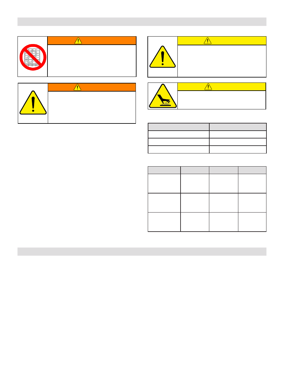
WARNING
Ensure proper guarding of the product is
used. Nexen recommends the machine
builder design guarding in compliance
with OSHA 29 CFR 1910 “Occupa-
tional Safety and Health Hazards.”
TABLE 4 Maximum Operating Speeds
Model
RPM
TCC-10
1500
TCC-14
1200
TCC-20
900
WARNING
DO NOT exceed maximum operating
speed (See Table 4). If you exceed
maximum operating speeds, you may
damage or decrease the performance
and the life of the Tension Control Clutch.
TABLE 5 Screw & Fastener Tightening Torques
Description
TCC-10
TCC-14
TCC-20
Rotor Set
Screw
(Item 7)
23 ft-lbs
[30.9 Nm]
50 ft-lbs
[67.5 Nm]
166 ft-lbs
[224.0 Nm]
Housing Set
Screw
(Item 26)
23 ft-lbs
[30.9 Nm]
50 ft-lbs
[67.5 Nm]
166 ft-lbs
[224.0 Nm]
Caliper Cap
Screw
(Item 18)
27 ft-lbs
[36.4 Nm]
50 ft-lbs
[67.5 Nm]
27 ft-lbs
[36.4 Nm]
Check all screws and fasteners for proper tightening torque
BEFORE operating the unit. (See Table 5). Overtighten-
ing tightening can cause the screws and fasteners to fail.
Under-tightening can reduce the performance of the Tension
Control Clutch.
For optimum clutch action, connect the controls as close to
the unit as possible. Nexen recommends the installation of
an air line filter in the air line ahead of the controls.
For automatic tension control, use Nexen’s Electronic
Tension Control System. Contact your local Nexen Web
Handling distributor or representative for information con-
cerning this product.
Inspect all cap screws and set screws on a regular basis and make sure they are tightened to the recommended torque.
Inspect the friction facings regularly and replace them when worn to approximately 5/32" [4 mm] thick.