Nexen TCC-7 835197 User Manual
Page 9
6
FORM NO. L-20176-C-0210
PARTS REPLACEMENT
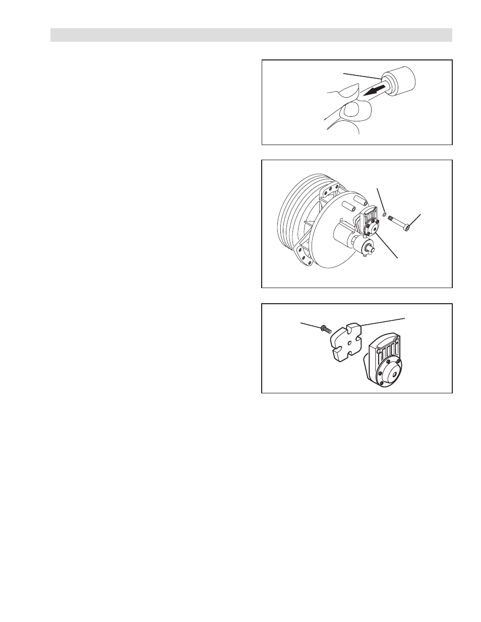
FIGURE 6
FIGURE 7
FRICTION FACING REPLACEMENT
Inspect friction facings and replace them when worn to
approximately 5/32" [4 mm] thick.
REFER TO FIGURES 5-7.
1. Stop machine and shut off the air supply to TCC-7.
2. Disconnect the Air Lines.
a. To disconnect the Air Line, push in on the
collar of the fitting and pull the Air Line out.
b. To reconnect the Air Line, push it into the
fitting until it stops.
3. Remove the Socket Head Cap Screws (Item 19) and
Lock Washers (Item 18).
4. Remove the Caliper Assembly from Housing.
5. Remove the Flat Head Screw (Item 10) from back
of the Caliper Assembly and remove the old Friction
Facing (Item 9).
6. Install a new Friction Facing (Item 9) and secure it to
the Caliper Assembly with a Flat Head Screw (Item
10). Tighten the Flat Head Screw to 18-19 in-lbs
[2.0-2.1 Nm].
7. Place the Caliper Assembly in position and secure it
to the Housing with Socket Head Cap Screws (Item
19) and Lock Washers (Item 18).
8. Tighten the Socket Head Cap Screws (Item 19) to
27 ft-lbs [36.4 Nm] torque.
9. Reconnect the Air Lines.
Friction
Facing
(Item 9)
Flat Head
Screw
(Item 10)
FIGURE 5
Push Collar in
to Release
Lock Washer
(Item 18)
Socket Head
Cap Screw
(Item 19)
Caliper
Assembly