Nexen TCC-7 835197 User Manual
Page 5
2
FORM NO. L-20176-C-0210
INSTALLATION
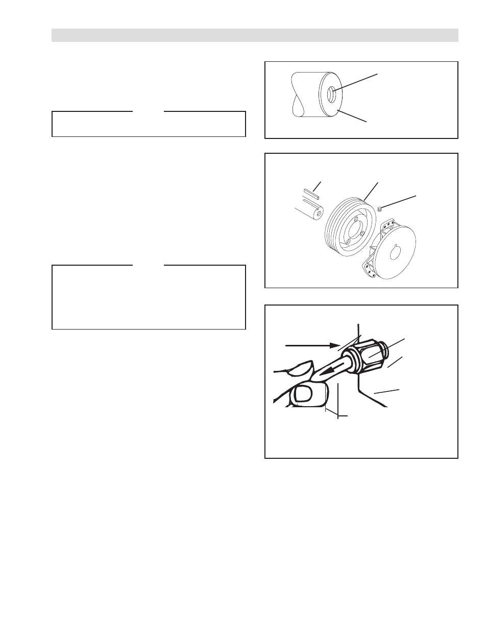
FIGURE 1
REFER TO FIGURES 1-3.
1. Drill a 37/64" diameter hole 1" deep and tap 5/8-18
UNF - 2A X 25/32" deep into the end of the Shaft.
NOTE
Nexen recommends using a Nexen Rotary Air
Union product number 835139.
2. Using customer supplied 1/4-20 UNC cap screws,
secure customer supplied sheave or sprocket to
TCC-7.
3. Insert Nexen supplied Key (Item 6) into machine
Shaft.
4. Slide TCC-7 onto machine shaft.
5. Tighten Set Screws (Item 3) to 7 ft-lbs [9.5 Nm
torque.
NOTE
Runout of the Friction Disc Hub (Item 2) must
be less than 0.015'' [0.381 mm] TIR. Runout
is minimized if a Dial Indicator is used as Set
Screws (Item 3) are tightened. Place contact tip
of Dial Indicator on machined surface of Friction
Disc Hub to measure runout.
6. Using a Flat Head Screw (Item 10) provided with
each Friction Facing (Item 9), secure a Friction
Facing to each Caliper Assembly.
7. Using Spacers (Item 5), Lock Washers (Item 18),
and Socket Head Cap Screws (Item 19), secure the
Caliper Assemblies to Housing (Item 1).
8. Tighten Socket Head Cap Screws (Item 19) to 25
ft-lbs [36.43 Nm] torque.
9. Install the Rotary Air Union into hole tapped into end
of shaft.
FIGURE 2
FIGURE 3
Center drill 37/64
Dia. x 1 " Deep.
Tap 5/8 - 18 UNF
-2A X 25/32" Deep.
Shaft
Key
Set Screw
Sheave or
Sprocket
Socket Head
Cap Screw
(Item 19)
Spacer
(Item 5)
Lock Washer
(Item 18)
Rotary Air Union
P/N 835139
1.62'' [41 mm] minimum between
shaft end and clutch disc.