Nexen TCC-7 835197 User Manual
Page 7
4
FORM NO. L-20176-C-0210
AIR CONNECTIONS
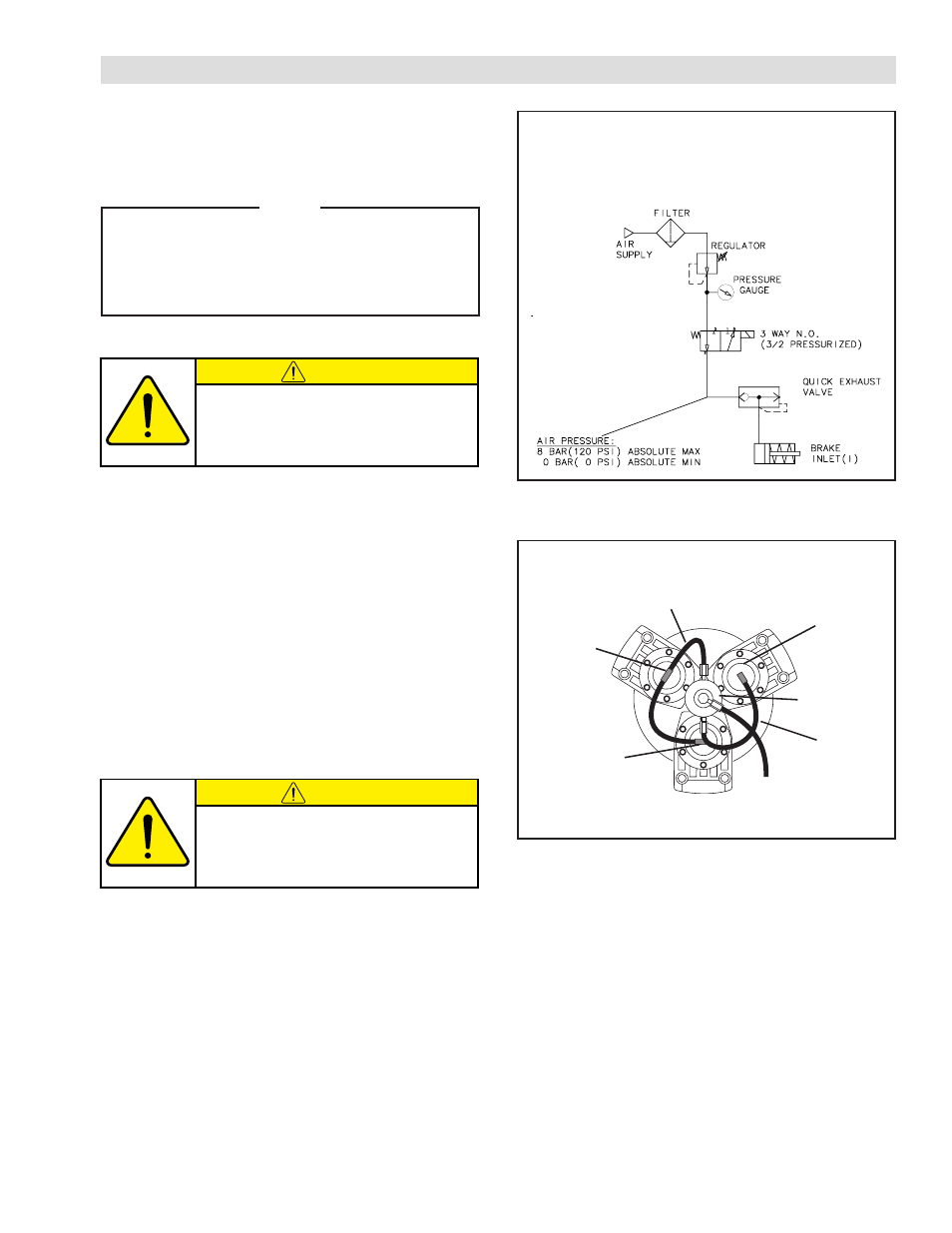
The following is a common air supply scheme used with
this product. This is an example and not an all-inclusive
list. All air circuits to be used with this product must
be designed following EN983 guidelines.
All Nexen pneumatically actuated devices require clean,
dry air that meets or exceeds ISO 8573.1:2001 Class
4.4.3 to quality.
CAUTION
Low air pressure will cause slippage and
overheating. Excessive air pressure will
cause abrupt starts and stops, reducing
product life.
NOTE
For quick response, Nexen recommends a quick
exhaust valve and short air lines between the
Control Valves and the unit. Align the air inlet
ports to a down position to allow condensation
to drain out of the air chambers of the product.
REFER TO FIGURE 4.
1. Install Elbow Fittings (Item 15) into two Caliper
Assemblies.
2. Install Tee Fitting (Item 16) into the remaining Caliper
Assembly.
3. Cut the Air Line (Item 17) to length and push it into
the fittings to make connections between the Rotary
Air Union, Elbow (Item 15), and Tee Fittings (Item
16).
FIGURE 4
CAUTION
In order to ensure proper balancing of
the TCC-7, all Air Lines must be cut to
the same length.
4. Route the remaining length of Air Line from the
Rotary Air Union inlet to the control output port or
connection.
5. Connect the air supply to the control input port or
connection.
Tee
Fitting
(Item 16)
Air Line
(Item 17)
Elbow
Fitting
(Item 15)
Rotary Air
Union
Air Line
(Item 17)
To Control
Elbow Fitting
(Item 15)