Nexen BD 933507 User Manual
Page 17
17
FORM NO. L-20063-AD-0314
6. Replace the Shoe Pins (Item 16) (See Figure 16).
Note
On spring engaged BD Caliper Brakes, apply hold-off air
pressure and:
o
BSolete
t
hree
-P
ort
a
ctuator
o
nly
Using a 9/16 inch socket, turn the top bolt clockwise until it
bottoms out (approximately 40 turns), then torque the Tap Bolt
to 13.5-20.2 Nm [10-15 ft-lb].
t
wo
-P
ort
a
ctuator
o
nly
Using a 3/4 inch socket, turn the tap bolt clockwise to fully uncage
(decompress) the spring. The spring is fully decompressed when
the hex bolt head is flush against the actuator.
60 PSi a
ctuator
o
nly
Using a 15/16 inch socket, turn the manual release bolt
12 turns counterclockwise to fully uncage (decompress)
the spring.
Remove hold-off air pressure.
7. Perform Friction Facing adjustment (See FRICTION
FACING CLEARANCE ADJUSTMENT).
2
12
8
16
3
18
4
18
3
16
FIGURE 16
Note
When replacing Friction Facings (Item 4), inspect the Friction
Disc for scoring or grooves. If necessary, the Friction Disc
may be turned. A total of 0.762 mm [0.030 in] may be
removed from each side of the Friction Disc before it is
necessary to replace the Friction Disc.
On spring engaged BD Caliper Brakes, apply hold-off air
pressure and:
o
BSolete
t
hree
-P
ort
a
ctuator
o
nly
Using a 9/16 inch socket wrench, turn the tap bolt counterclockwise
until the brake is released (approximately 40 turns). Hold-off air
pressure can be removed at this time and service performed.
t
wo
P
ort
a
ctuator
o
nly
Using a 3/4 inch socket, turn the tap bolt counterclockwise to fully
cage (compress) the spring. The spring is fully compressed when
the bolt is backed out of the unit 21 mm [0.83 inches].
60 PSi a
ctuator
o
nly
Using a 15/16 inch socket, turn the manual release bolt
clockwise until snug to fully cage (compress) the spring.
1. Remove Shoe Pins (Item 16) to release Friction Facing
Shoe Assembly (Items 3 and 4) from Arms (Item 2) (See
Figure 16).
2. Remove Friction Facings (Item 4) from the Shoes
(Item 3) by removing the Machine Screws (Item 18)
(See Figure 15).
3. Install new Friction Facings using new Machine Screws
(Item 18) (See Figure 16).
4. Tighten the Machine Screws to 12-15 Nm [8-12 ft-lb]
torque.
5. Loosen adjustment screw Spanner Nut (Item 12) and
back out Adjustment Screw (Item 8) until the Friction
Facings (Item 4) and Shoes (Item 3) will slide back
into the Arms (Item 2) (See Figure 16).
PARTS REPLACEMENT
FRICTION FACINGS
60 PSi a
ctuator
o
nly
Note
The Hex bolt on the back of the actuator canister can
be used to physically release the spring in the event
of actuator failure or machine service without hold
off air available. DO NOT USE THE TAP BOLT TO
ADJUST FRICTION FACING GAP. This will lower torque
capabilities. If the actuator (spring-engaged units
only) is damaged and air pressure will not release the
brake, use a 15/16 inch socket wrench to turn the tap
bolt clockwise until the brake is released. The spring
is fully compressed when the bolt is snug.
D
iSengagement
1. If a manual release for safety reasons is needed, first
apply hold off air pressure to remove any tension on
the Tap bolt for easier release.
2. Using a 15/16 inch socket, turn the manual release
bolt clockwise to fully cage (compress) the spring. The
spring is fully compressed when the bolt is snug (Refer
to Figure 15c).
3. Hold off air pressure can be removed at this time and
service performed.
r
e
-
engagement
1. To reengage the actuator, apply hold off air pressure.
2. Using a 15/16 inch socket, turn the manual release
bolt counterclockwise to fully uncage (decompress)
the spring. The spring is fully decompressed when the
hex bolt head is flush against the actuator.
3. Remove hold off air pressure.
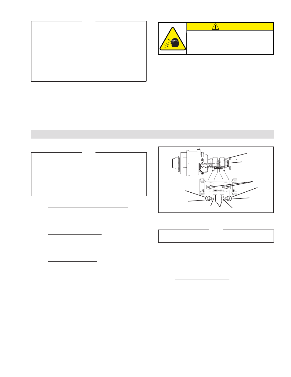
CAUTION
This product is spring loaded under
extreme pressure. Do not disassemble.
actuator. If actuator malfunctions, replace
actuator or contact Nexen.