Maintenance – Nexen BD 933507 User Manual
Page 15
15
FORM NO. L-20063-AD-0314
TABLE 4
M
E
T
I
N
O
I
T
P
I
R
C
S
E
D
E
U
Q
R
O
T
4
2
s
w
e
r
c
S
p
a
C
]
b
l-
tf
7
-
5
[
m
N
9
-
7
--
g
n
i
R
p
m
a
l
C
r
o
t
a
u
t
c
A
)t
u
N
d
n
a
tl
o
B
(
]
b
l-
tf
5
3
-
5
2
[
m
N
2
.
7
4
-
7
.
3
3
9
1
s
w
e
r
c
S
p
a
C
]
b
l-
tf
0
5
[
m
N
5
.
7
6
2
1
t
u
N
r
e
n
n
a
p
S
]
b
l-
tf
5
1
-
0
1
[
m
N
3
.
0
2
-
6
.
3
1
--
e
b
u
T
g
n
it
n
u
o
M
r
o
t
a
u
t
c
A
)t
u
N
r
e
n
n
a
p
S
(
]
b
l-
tf
5
1
-
0
1
[
m
N
3
.
0
2
-
6
.
3
1
--
tl
o
B
p
a
T
)
y
l
n
o
d
e
g
a
g
n
e
-
g
n
ir
p
S
(
]
b
l-
tf
5
1
-
0
1
[
m
N
3
.
0
2
-
6
.
3
1
8
1
w
e
r
c
S
e
n
i
h
c
a
M
]
b
l-
tf
2
1
-
8
[
m
N
5
1
-
2
1
1. Adhere to the following bolt torques (See Table 4).
2. Clean Breather Cap air filter when dirty (spring engaged
unit only).
3. Inspect canister exterior for damage. Replace canister
if damaged.
4. Check tightness of all air line connections and condition
of all air lines. Replace air lines if deterioration exists.
5. Inspect friction facings for wear. Replace if worn to
approximately 5/32 inch thick.
6. Lubricate items requiring lubrication (See
LUBRICATION).
MAINTENANCE
The use of 3/4 inch wide discs with the BD Caliper Brake requires a shorter Piston Rod (Item 10) and Return Springs
(Item 17) for proper operation. (Not applicable for the 60 psi canister.)
OPTION KIT FOR 3/4" WIDE DISC INSTALLATION (INCLUDED WITH BRAKE)
1. Remove Return Spring (Item 17) and Shoes (Item 3)
by removing Shoe Pins (Item 16) (See Figure 15).
2. Loosen the Spanner Nut (Item 12) and turn the
Adjustment Screw (Item 8) counterclockwise until it is
fully disengaged (See Figure 15).
3. Open the Arms (Item 2) at the actuator end and replace
the Piston Rod (Item 10) (See Figure 17).
4. Reinstall the Shoes (Item 3), Shoe Pins (Item 16), and
Return Spring (Item 17) (See Figure 15).
5. Reengage the brake.
NOTE
On spring engaged BD Caliper Brakes, apply hold-off
air pressure and:
o
BSolete
t
hree
-P
ort
a
ctuator
o
nly
Using a 9/16 inch socket, turn the top bolt clockwise
until it bottoms out (approximately 40 turns), then torque
the Tap Bolt to 13.5-20.2 Nm [10-15 ft-lb].
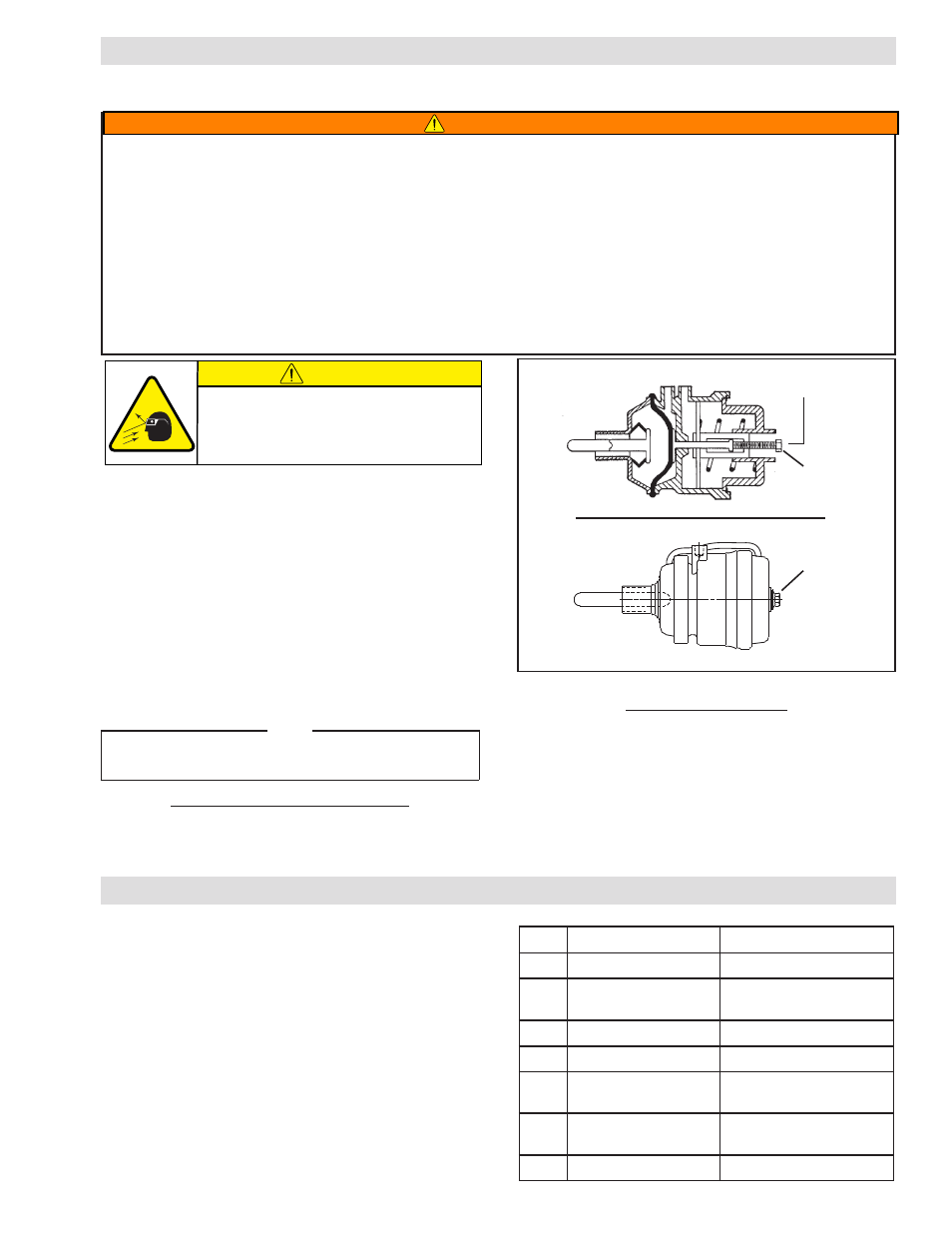
Tap Bolt located under
Breather Cap.
Figure 15a
Figure 15b
9/16" Hex
Head
3/4" Hex
Head
WARNING
Spring actuated brakes must be manually released prior to brake disassembly.
o
BSolete
t
hree
-P
ort
a
ctuator
Apply hold-off air pressure to remove tension on the Tap Bolt and use a 9/16 inch socket wrench to turn the Tap Bolt
counterclockwise until the brake is released (approximately forty turns).
t
wo
-P
ort
a
ctuator
Apply hold off pressure to remove tension on the Tap Bolt and use a 3/4 inch socket wrench to turn the Tap Bolt counter
clockwise to fully cage (compress) the spring. The spring is fully compressed when the bolt is backed out of the unit 21 mm
[0.83 in].
Hold-off air pressure can be removed at this time, and service performed (See Figure 15 a & b).
WARNING
t
wo
-P
ort
a
ctuator
o
nly
Using a 3/4 inch socket, turn the tap bolt clockwise to
fully uncage (decompress) the spring. The spring is
fully decompressed when the hex bolt head is flush
against actuator.
6. Perform friction facing adjustment (See FRICTION
FACING CLEARANCE ADJUSTMENT).
CAUTION
Working with spring loaded or tension
loaded fasteners and devices can cause
injury. Wear safety glasses and take the
appropriate safety precautions.