Installation (continued) – Nexen DPC-13T 962200 User Manual
Page 6
6
FORM NO. L-20093-L-1209
TABLE 3
N
O
I
T
P
I
R
C
S
E
D
T
3
1
-
C
P
D
T
5
1
-
C
P
D
)
1
2
m
e
tI
(
w
e
r
c
S
p
a
C
.
T
F
9
1
1
.
S
B
L
.
T
F
9
1
1
.
S
B
L
0
2
m
e
tI
(
t
u
N
k
c
o
L
.
T
F
0
7
.
S
B
L
.
T
F
0
7
.
S
B
L
s
tl
o
B
P
U
-l
l
u
P
.
T
F
5
7
.
S
B
L
.
T
F
2
1
1
.
S
B
L
NOTE: Do not use lubricants or thread locking
compounds on Pull-Up Bolts.
9. Using a Dial Indicator, measure runout of motor shaft.
Runout must not exceed 0.002 T.I.R. (Total Indicated
Reading).
10. Insert Key into motor shaft keyway.
11. Slide the DPC Clutch inner assembly onto the motor
shaft.
NOTE
There must be a gap of approximately 1/32" between
the Friction Facing (Item 4), and the friction surface
of the Flange Mount Disc (Item 5). To obtain this
1/32" gap; insert three equally spaced 1/32" shims
between the Friction Facing and the Friction surface
of the Flange Mount Disc, and clamp the DPC inner
assembly, and the Flange Mount Disc together at
each shim location.
12. Alternately, and evenly, tighten Q.D. Bushing Pull-Up
Bolts to the recommended torque (See Table 3).
NOTE
To avoid preloading of the bearings; the motor shaft
must be free to “float” when tightening the Q.D.
Bushing Pull-Up Bolts.
NOTE
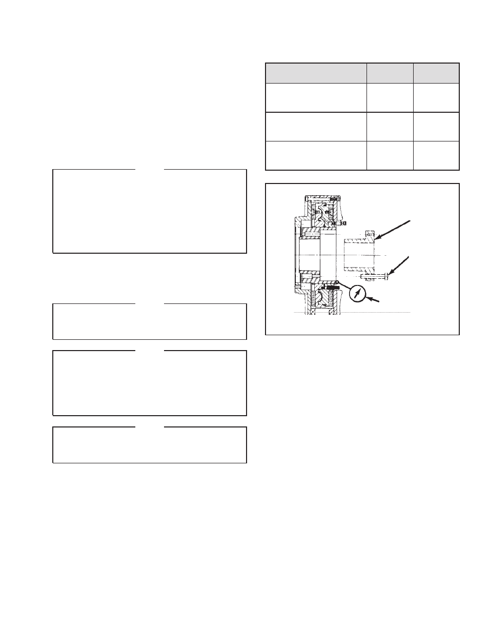
Runout is minimized if a Dial Indicator is used as the Q.D.
Bushing Pull-Up Bolts are tightened. Place the contact
tip of the Dial Indicator on the machined surface of the
Splined Hub to measure runout. Runout at this surface
must be within 0.003 T.I.R when the Pull-Up Bolts are
tightened.
NOTE
Do not over tighten Pull-Up Bolts. If excessive
tightening torque is applied; bursting pressure is
created in the Splined Hub.
13. Remove all shims and clamps.
14. Install the Housing (Item 6), and Friction Disc (Item 7),
and secure them with Lock Nuts (Item 20).
15. Tighten the Lock Nuts (Item 20) to the recommended
torque (See Table 3).
INSTALLATION (continued)
FIGURE 2
Dial
Indicator
Pull-Up
Bolts
Q.D. Bushing