Introduction, Installation – Nexen DPC-13T 962200 User Manual
Page 5
5
FORM NO. L-20093-L-1209
INTRODUCTION
Nexen’s modularized DPC (Dual Friction Plate) Clutches
are designed to mount on shaft ends, or on through shafts
using customer supplied Q.D. (Quick Detachable) Bushings.
The dual friction plate design eliminates thrust loading of
bearings when the DPC Clutch is connected to the Pilot
Assembly, or a bearing supported Flywheel, Sheave, or
Sprocket.
Seven components are combined to install Nexen’s DPC
Clutch as an Element Clutch, Pilot Mount Clutch, or a
Sheave Clutch.
The seven basic components (each sold separately) are:
DPC”Clutch, Q.D. Bushing (customer supplied), Rotary Air
Union (supplied with DPC Clutch), Rotary Air Union Cap,
Sheave, Pilot Assembly, and Bushing.
The inner and outer assemblies of the DPC Clutch rotate
independently.
When mounted of a through shaft, the outer clutch assembly
rotates, and upon engagement, the inner clutch assembly
becomes the driven member.
When mounted on a continually running shaft, the inner
clutch assembly rotates, and upon engagement, the outer
clutch assembly becomes the driven member.
Nexen recommends mounting the DPC Clutch with the outer
clutch assembly rotating continuously; taking advantage
of the cooling effect of the fin to dissipate heat generated
when the clutch is engaged.
INSTALLATION
NOTE: All DPC Clutch installations require a Q.D. (Quick
Detachable) Bushing. Refer to Table 1 for Q.D.
Bushing Specifications.
ELEMENT CLUTCH
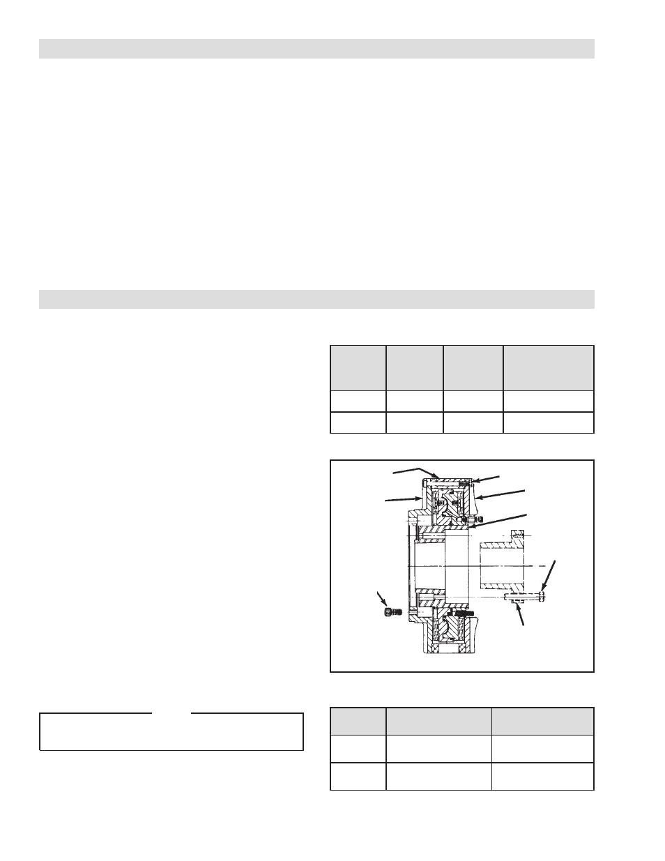
Refer to Figures 1 & 2.
1. Remove Lock Nuts (Item 20).
2. Remove Friction Disc (Item 7), and Flange Mount
Housing (Item 6) from Flange Mount Disc (Item 5).
3. Set DPC inner assembly aside.
4. Using Cap Screws (Item 21), attach Flange Mount Disc
(Item 6) to bearing supported component. (See Table
2).
5. Tighten Cap Screws (Item 21) to recommended torque
(See Table 3).
6. Thoroughly inspect the tapered bore of the Splined
Hub (Item 1), and tapered surface of the Q.D. Bushing.
Remove any dirt, grease, or foreign material.
7. Install Q.D. Bushing into Splined Hub (Item 1); aligning
untapped holes in Q.D. Bushing with tapped holes in
Splined Hub.
NOTE
Do not strike the Q.D. Bushing to set it in the tapered
bore.
8. Loosely insert the Q.D. Bushing Pull-Up Bolts, and
Lockwashers into the Q.D. Bushing, and the tapped
holes of the Splined Hub.
TABLE 1
L
E
D
O
M
G
N
I
H
S
U
B
E
P
Y
T
M
U
M
I
X
A
M
E
R
O
B
T
L
O
B
P
U
-
L
L
U
P
G
N
I
N
E
T
H
G
I
T
E
U
Q
R
O
T
T
3
1
-
C
P
D
F
0
0
5
.
3
.
S
B
L
.
T
F
5
7
T
5
1
-
C
P
D
J
0
0
0
.
4
.
S
B
L
.
T
F
2
1
1
FIGURE 1
5
6
20
1
7
Pull-Up
Bolts
Q.D. Bushing
21
TABLE 2
L
E
D
O
M
E
L
C
R
I
C
T
L
O
B
S
E
L
O
H
T
L
O
B
T
3
1
-
C
P
D
]
m
m
5
5
.
9
0
2
[
"
0
5
2
.
8
d
e
c
a
p
S
y
ll
a
u
q
E
6
T
5
1
-
C
P
D
]
m
m
0
6
.
8
2
2
[
"
0
0
.
9
d
e
c
a
p
S
y
ll
a
u
q
E
6