Power cooler and discharge tube mounting – Vortech 1999 & 2001 Ford 4.6L Mustang Cobra User Manual
Page 11
P/N: 8N020-060
© 2001 Vortech Engineering, LLC
All Rights Reserved, Intl. Copr. Secured.
26APR01 V1.0 (4V Maxflow PwrClr(8N020-060).qxd)
3
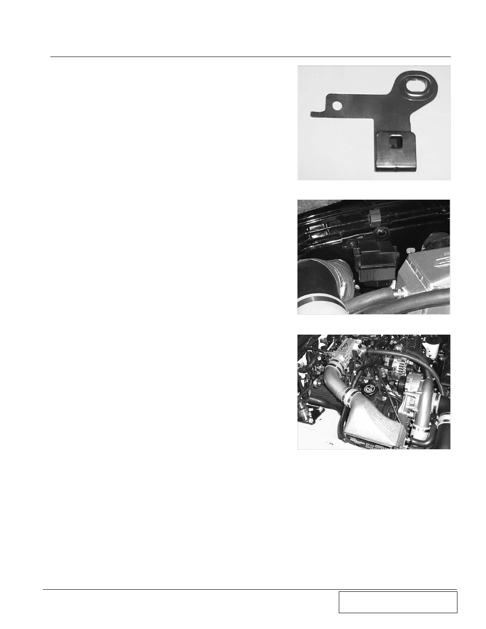
3. Power Cooler and Discharge Tube Mounting
A.
Remove the fuse box located near the passen-
ger’s side strut tower with a 10mm wrench and
detach the two plastic wiring harness anchors.
Separate the bracket from the fuse box. Drill a 1/4”
hole in the bracket as shown (see Fig. 3-a).
Secure the bracket to the inner fender using the
factory airbox bolt and clip-nut (see Fig. 3-b).
B.
Install the bypass valve onto the 1” cooler inlet
barb using the original hose. Secure the assembly
to the Power Cooler.
C.
Remove the silicone sleeves and clamps from the
original discharge tube.
D.
Install the 2 3/4” diameter silicone sleeve onto the
supercharger outlet and slide the sleeve back as
far as possible, leaving the two #44 hose clamps
loose.
E.
Slide the supplied 3-1/2” to 3” silicone reducer
sleeve and clamp onto the aftercooler outlet. Put
the #56 hose clamp on the other end of the reduc-
er. Leave the two hose clamps loose.
F.
Reinstall the original 4-1/2” sleeve onto the throttle
body leaving the two #72 hose clamps loose.
G. With cooler into position, slide the silicone sleeve
and clamps from the supercharger outlet onto the
aftercooler inlet and secure.
H.
Install the discharge tube between aftercooler and
throttle body and secure sleeves and clamps. (See
Fig. 3-c.)
I.
Reconnect the bypass valve outlet to the 90° plas-
tic elbow on the air inlet and secure with the origi-
nal hose clamps. A small amount of trimming to
the 1” hose may be necessary to ensure proper fit.
Fig. 3-a
Fig. 3-c
Fig. 3-b