Vortech 1992-1996 5.7L LT1 Corvette User Manual
Page 25
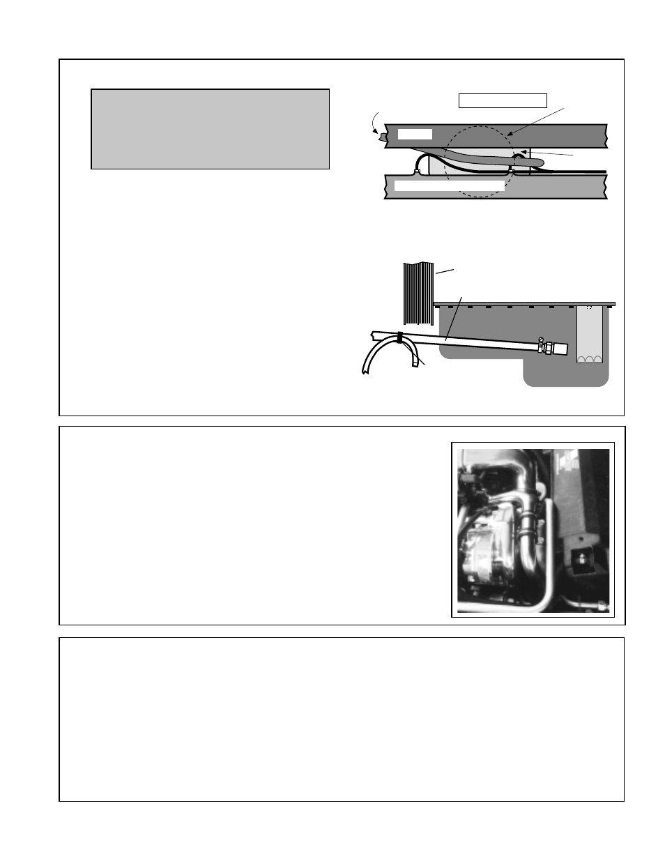
FROM
SUPERCHARGER
OIL PAN
VIEW FROM FRONT
FRAME
CRANK
PULLEY
POWER STEERING RACK
ROUTE THE DRAIN HOSE AROUND THE CRANK
PULLEY AND BACK TO THE 1/2" BARB IN THE PAN
OIL PAN
TIE WRAP
TO POWER
STEERING LINE
OIL DRAIN HOSE
DAMPENER PULLEY
FIG. B
15. DRAIN LINE
A. Route the supercharger drain hose downward
behind the front frame crossmember.
Using tie wraps, secure the drain hose to the
steel power steering pressure line located on
the steering rack. See fig. A.
B. Route the drain hose around the front of the
crank pulley to the driver's side of the engine.
Make sure that the hose maintains smooth
downhill routing.
C. Use tie wraps to secure the hose to the rear
power steering line, away from the crank
pulley and accessory belt. See fig. A and B.
D. Attach the end of the drain hose to the 1/2"
drain fitting barb in the oil pan and secure with
the supplied #8 hose clamp. Trim the hose
length if necessary.
15
NOTE: It is important that the super-
charger oil drain line be routed
gradually downward without dips,
away from heat, sharp objects and
moving parts.
16. RADIATOR PIPE
A. Install the previously cut radiator hoses on the radiator and
water neck with OEM clamps.
B. Install the supplied stainless coolant pipe and #24 clamps.
C. Install the two adel clamps, #10-24 x 1/2" screws and #10
washers to hold the coolant pipe in place on top of the air
inlet duct.
17. DISCHARGE TUBE
A. Using the #44 clamps, place the 2-3/4" blue sleeve onto the
supercharger discharge. Place the large sleeve onto the
throttle body using #72 clamps.
B. Install the discharge tube and secure with the clamps to the
supercharger and throttle body.
C. Hook up the IAT sensor connector.
D. Connect the length of 7/8" hose from the bypass valve to the
barb on the air inlet duct with the #16 hose clamps. Trim the
hose, if necessary.
FIG. A