Vortech 2004 Pontiac GTO User Manual
Page 18
10
P/N: 4GJ020-010
©2004 Vortech Engineering, LLC
All Rights Reserved, Intl. Copr. Secured
28SEP04 v1.0 GTO(4GJ020-010v1.0)
8.
SUPERCHARGER MOUNTING
G.
Using the six supplied 1/4-20 x .75" SHCS
secure the anodized drive pulley on the drive
hub. Torque the screws to 16 ft/lbs. (Blue loc-
tite is recommended on the 1/4" hardware.)
(See Fig. 8-l.)
H.
Reinstall the factory belt with the factory belt
routing.
I.
Install the oil drain line on the supercharger
and secure it with the supplied #8 hose
clamp.
J.
Using a 23/32" drill make a hole in the alu-
minum inlet duct as shown in Fig. 8-f. Drill the
hole leaving at least .75" from the lip.
K.
Install the T-bolt clamp onto the inlet duct,
then place the inlet duct on the supercharger.
Orient the duct as shown in figures 8-g, 8-h.
Tighten the t-bolt clamp so that the inlet duct
is snug. When the supercharger and inlet
duct are installed the clocking of the inlet duct
can be fine tuned.
Fig. 8-a
Fig. 8-b
Fig. 8-c
NOTE: When installing the aluminum drive pulley heat
may be necessary for installation due to tight
tolerances. Do not force the pulley on the hub.
After the pulley is installed spin it to verify that
the hub and pulley are mated flush.
A.
Turn the power steering pump sideways and
install the supplied power steering/super-
charger drive pulley hub. Make sure that the
hub is seated flush with the end of the
power steering pump shaft. (See Fig. 8-c.)
B.
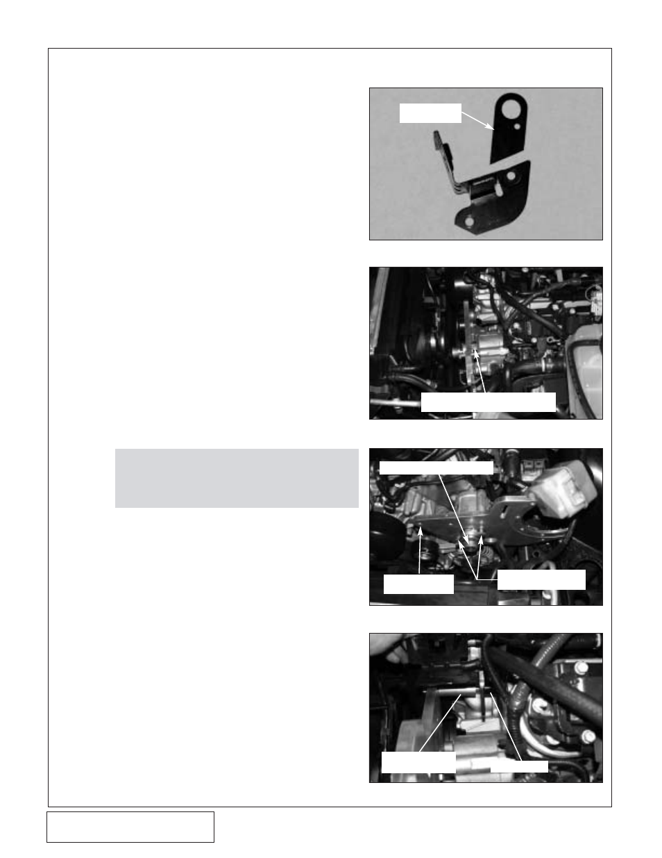
Locate the power steering reservoir bracket.
The engine lift hook will have to be removed
from the bracket. Use a saw or grinder and
remove the section as shown in Fig. 8-a.
C.
Using two 10mm x 1.5 x 110mm screws,
washers and .430 spacers, secure the mount-
ing bracket to the front of the power steering
pump. Use the .430 spacers between the
pump and back of the plate. (See Fig. 8-c.)
D.
For the third mounting location, use a 10mm
x 1.5 x 110mm screw, 10mm washer, 2.2"
spacer, power steering bracket and .880"
spacer. The 10mm screw will pass through
the washer, mounting plate, 2.2" spacer, left
hole in power steering reservoir bracket,
.880" spacer and thread into the head. (See
Fig. 8-d.)
E.
Using the other supplied .880 spacer and
10mm x 1.5 x 40mm screw secure the last
hole of the power steering reservoir bracket
into its factory position.
F.
Reinstall the power steering reservoir back
into the holder bracket. (See Fig. 8-e.)
Fig. 8-d
.430 SPACERS BETWEEN THE PLATE
AND P/S PUMP IN TWO LOCATIONS
FIRST TWO MOUNTING
LOCATIONS
THIRD MOUNTING
LOCATION
SUPERCHARGER DRIVE HUB
THIRD MOUNTING
PLATE LOCATION
.880" SPACER
SECTION TO BE
REMOVED