Vortech 2004 Pontiac GTO User Manual
Page 11
3
P/N: 4GJ020-010
©2004 Vortech Engineering, LLC
All Rights Reserved, Intl. Copr. Secured
28SEP04 v1.0 GTO(4GJ020-010v1.0)
A.
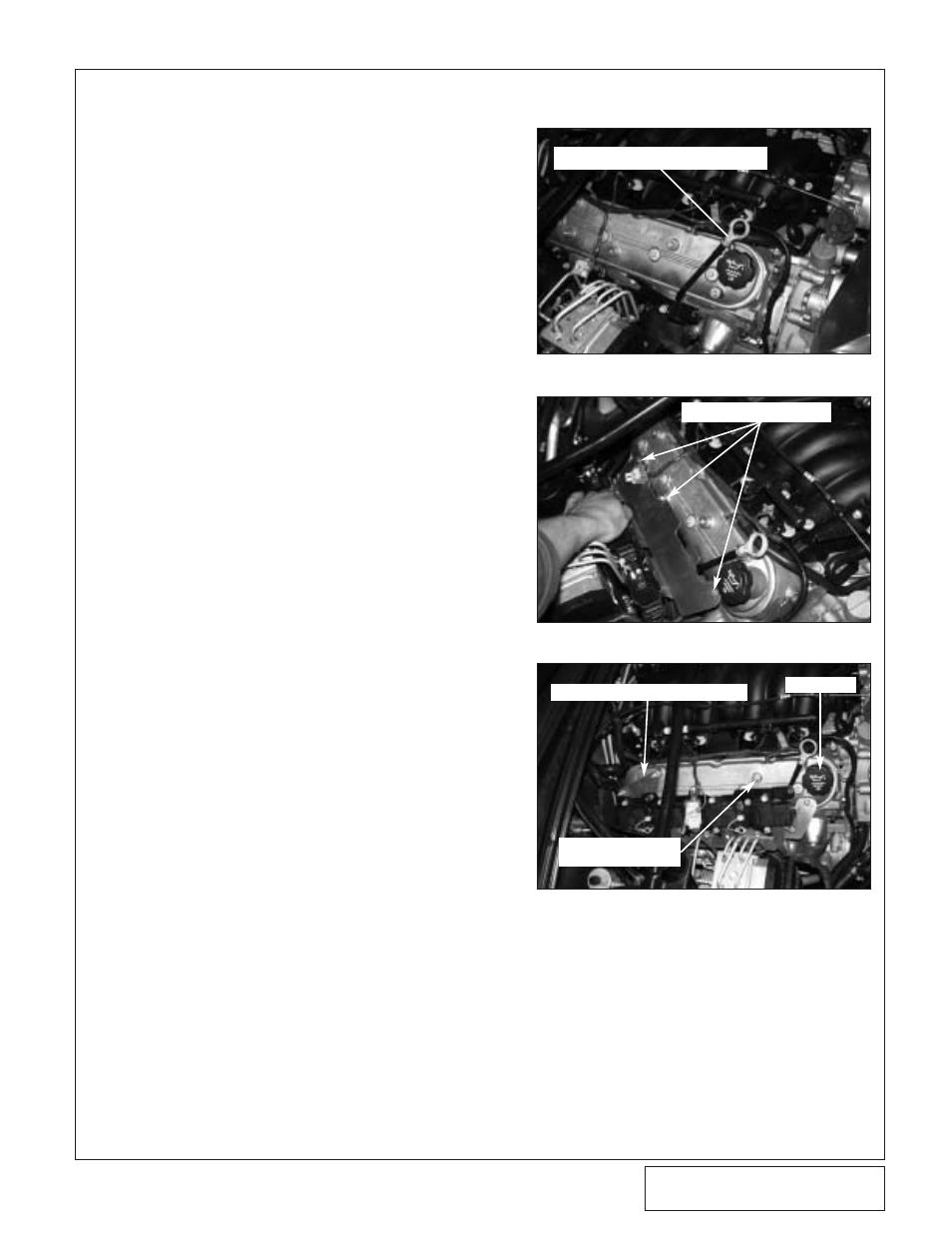
Locate the coils and their bracket on the pas-
senger side of the vehicle.
B.
Remove the coils and bracket from the valve
cover as one assembly leaving the plug wires
attached. Let the assembly rest against the
inner fender. Unplug the wiring harness from
the coil assembly. (See Fig 2-a.)
C.
Gently bend the oil dip stick tube forward and
in toward the valve cover. (See Figs 2-a, 2-b.)
D.
Using three 6mm x 1.0 x 16mm screws and
washers secure the supplied heat shield to
the lower row of holes on the valve cover.
Make sure the dipstick is located between the
heat shield and the valve cover.
E.
Using factory hardware, mount the triangular
coil relocation bracket to the upper rear holes
on the passengers side valve cover. Using
the supplied 6mm x 1.0 x 16mm hardare,
mount the secondary coil relocation bracket
on the upper forward most hole location.
Make sure the threaded holes hang down for
the coil bracket to mount to.(See Fig 2-c.)
F.
Using the supplied 6mm x 1.0 x 16mm
screws and washers mount the coil bracket to
the installed relocation brackets. (See Fig.
2-c.)
G.
Reconnect the harness plug.
2.
IGNITION COIL RELOCATION
Fig. 2-a
Fig. 2-b
Fig. 2-c
DIPSTICK BENT AGAINST VALVE COVER
3 MOUNTING LOCATIONS
TRIANGULAR RELOCATION BRACKET
OIL FILL CAP
SECONDARY
RELOCATION BRACKET