Vortech GM 5.3L/6.2L Light Truck/SUV - 2007-2008 User Manual
Page 19
P/N: 4GL020-018
©2008 Vortech Engineering, LLC
All Rights Reserved, Intl. Copr. Secured
11NOV08 GM Trk/H2(4GL..018v2.0)
9
8.
CHARGE COOLER INSTALLATION
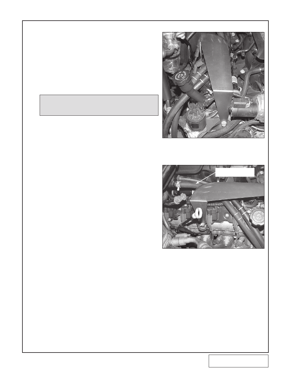
A. Remove the screw from the front of the pas-
senger side head. Remove the 10mm nut
located between the middle coil packs on the
passenger side valve cover, below the white
electrical connector. (See Figs. 8-a, 8-b.)
B. Install the charge air cooler support bracket
using the fasteners supplied. (See Figs. 8-a,
8-b.) Apply adhesive foam to the top of the
support bracket where the charge air cooler
rests. Make sure all hoses and wires are
clear from the bracket edges.
Fig. 8-a
Fig. 8-b
SECURE HOSES AWAY
FROM BRACKET
C. Slightly bend both the transmission and
engine oil dipsticks up and away to give
clearance for the charge air cooler.
D. Install the nickel plated 1/2"NPT x 3/4 90°
and straight brass fittings into the charge air
cooler using thread sealant on the threads.
(See Fig. 8-d.)
E. Install a 20-inch piece of 3/4 hose to the 90°
fitting and secure with a nylon clamp.
F. Attach the long 90° formed hose to the
straight barbed fitting on the charge cooler.
(See Fig 8-c).
G. Set the charge air cooler on the support with
the 90° brass fitting in the upper left corner
facing toward the passenger’s side. Using the
2-3/4" sleeves and #44 hose clamps, connect
discharge tube “A” to the discharge of the
supercharger and to the inlet of the charge air
cooler (See Fig 8-e).
NOTE: On later model trucks there will be no EGR assembly. Use the
supplied 10mm x 1.5" screw, washer and .975" spacer in its
place. (See Fig. 8-a.)