Vortech GM 5.3L/6.2L Light Truck/SUV - 2007-2008 User Manual
Page 16
P/N: 4GL020-018
©2008 Vortech Engineering, LLC
All Rights Reserved, Intl. Copr. Secured
11NOV08 GM Trk/H2(4GL..018v2.0)
6
6.
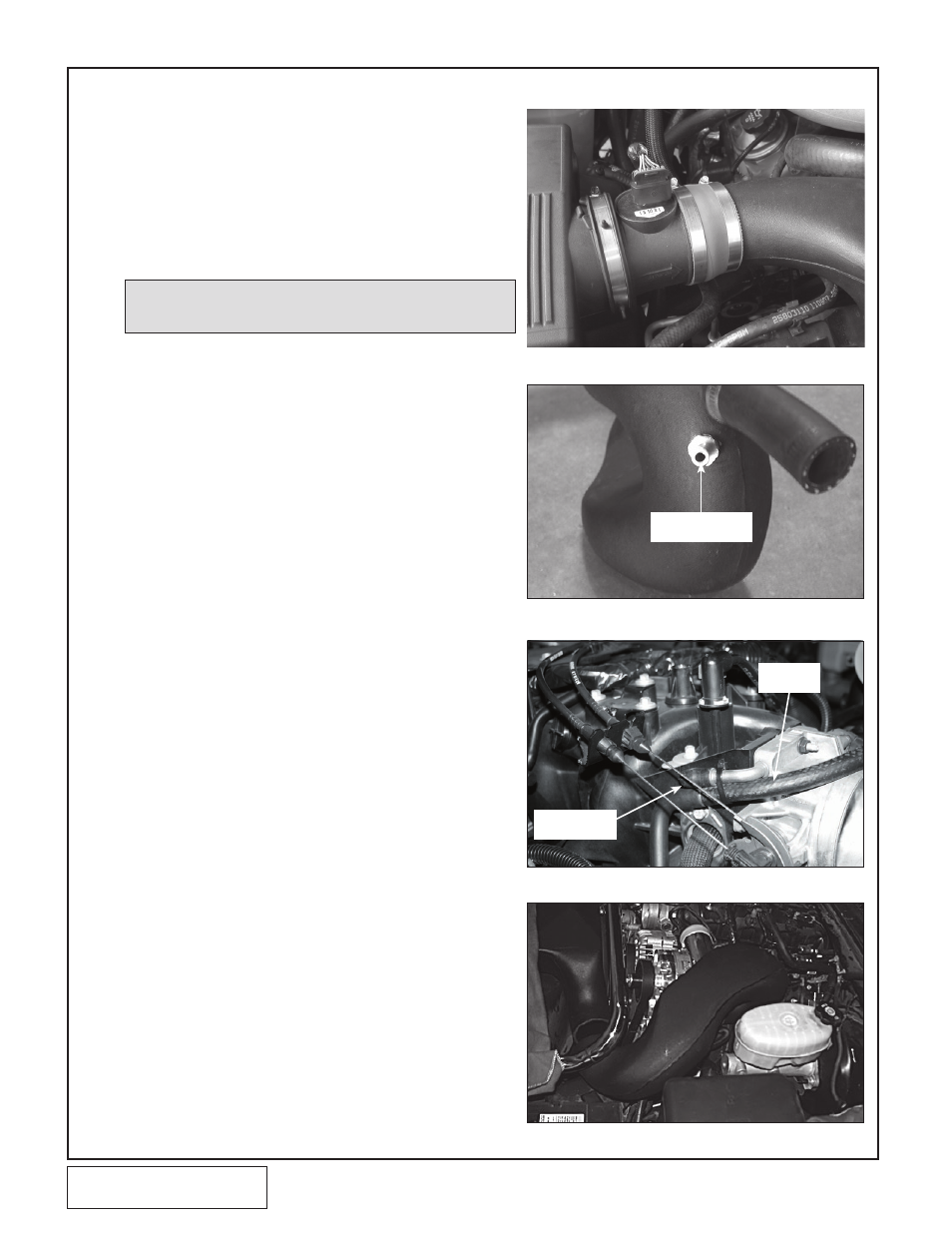
INLET DUCT INSTALLATION
A. Install the supplied 3.7"x3.5" reducer sleeve
onto the MAF outlet, and the 3-1/2" x 2"
sleeve on the inlet of the supercharger.
B. Remove any plastic clips that are no longer
used to secure the OEM radiator hose.
C. Slide the entry of the large plastic inlet duct
into the sleeve installed on the MAF (See Fig.
6-a). Lower the inlet duct onto the top of the
radiator shroud.
D. Insert the supplied 1/4-20 x 1/2" screws
through the bracket and into each side of the
inlet duct using the supplied washers. Tighten
the screws. (See Fig 6-a.)
E. Using Fig. 6-b, drill a 9/16" hole in the shown
location. Use a 3/8"NPT tap and install the
supplied 3/8" NPT x 3/8" hose barb.
F. Install the supplied 180° inlet duct onto the
inlet of the supercharger after the supercharg-
er is installed. Orient the duct so that it
"swoops" over the side of the supercharger
with the end pointing at the crossover duct.
(See Fig 6-d.)
G. Install the supplied #52 hose clamps and
3-1/2" x 7" long flex hose between the two
ducts previously installed. Trim hose if need-
ed.
H. Use the supplied 3/8" hose from the 3/8" fit-
ting on the inlet duct to the passenger side
valve cover breather hose. Secure the hose
so that it cannot interfere with the throttle arm
or cable. (See Fig 6-c.)
I. Install and tighten the hose clamps on each
connection. (See Fig. 6-a.)
Fig. 6-b
Fig. 6-c
Fig. 6-d
SUPPLIED
3/8" HOSE
SUPPLIED 3/8"
RUBBER CAP
NEW LOCATION
TO DRILL
Fig. 6-a
NOTE: The end of the plastic inlet duct that fits into the MAF sleeve
may require trimming on some applications.