Directed Electronics MERLIN 2000 User Manual
Page 13
© 2001 Directed Electronics, Inc. Vista, CA
13
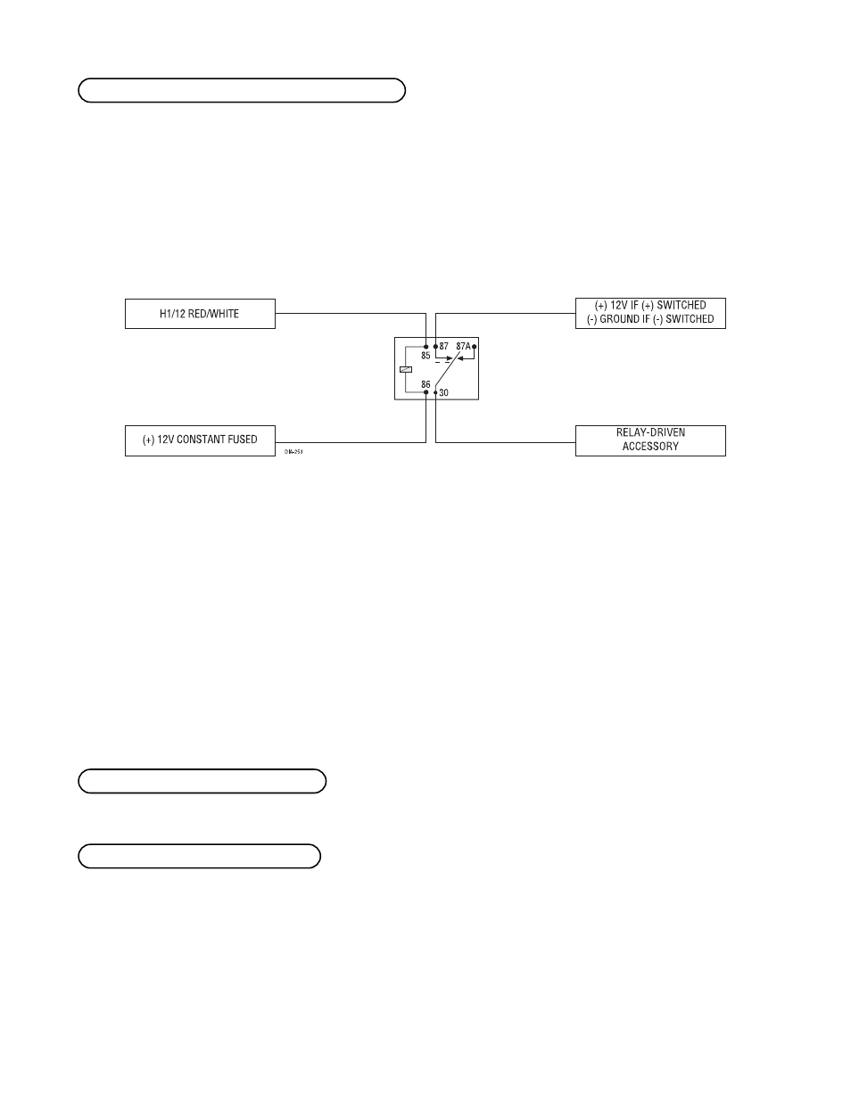
When the system receives the code controlling Channel 2 for longer than 1.5 seconds, the red/white wire will
supply an output as long as the transmission continues. This can be used to operate an optional relay-driven
function.
IMPORTANT! Never use this wire to drive anything but a relay or a low-current input! The transis-
torized output can only supply 200 mA of current. Connecting directly to a solenoid, motor, or other
high-current device will cause it to fail.
This output can be programmed to provide the following types of outputs (see System Features Learn Routine
section of this guide):
■ When the transmitter button(s) controlling Channel 2 is pressed for longer that 1.5 seconds, a delayed valid-
ity output will send a signal as long as the transmission is received.
■ A latched output will send a signal continuously when the Channel 2 transmitter button(s) is pressed and
will continue until the button(s) is pressed again.
■ A latched/reset with ignition output works similar to the latched output, but will also reset (output will
stop) when the ignition is turned on then off.
■ A 30-, 60- or 90-second timed output will send a signal for 30, 60, or 90 seconds, respectively, when the
Channel 2 transmitter button(s) is pressed.
Refer to H1/10 BLACK/WHITE starter kill wire description.
Refer to H1/6 WHITE (+) light flash output wire description.
H1/14 WHITE (+) light flash output
H1/13 BLACK/WHITE starter kill wire
H1/12 RED/WHITE channel 2, 200mA (-) output