Directed Electronics MERLIN 2000 User Manual
Page 12
12
© 2001 Directed Electronics, Inc. Vista, CA
Connect this wire to an ignition wire as described in the Finding the Wires You Need section of this manual. This
wire must show (+)12V with the key in the run position and during cranking. Make sure that this wire cannot be
shorted to the chassis at any point.
The siren should be mounted away from excessive heat sources, such as the exhaust manifold. Connect the H1/9
wire to the brown wire of the siren. For the remaining siren connections, refer to the Making Siren Connections
section of this guide.
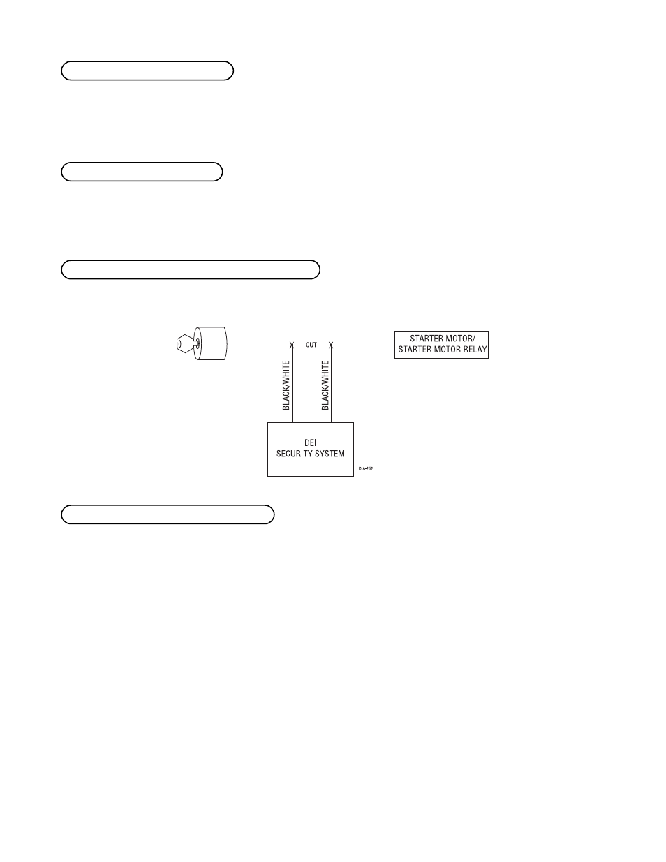
Use one of these wires as a starter kill input and the other as a starter kill output (these wires are interchangeable).
This wire provides a (-) 200 mA output whenever the transmitter button(s) controlling Channel 3 is pressed. This
output can be programmed to provide the following types of outputs (see System Features Learn Routine section
of this guide):
■ An instant validity output will send a signal immediately when the buttons controlling Channel 3 are
pressed. The signal will last as long as the transmission is received.
■ A latched output will send a signal continuously when the Channel 3 transmitter button(s) is pressed and
will continue until the button(s) is pressed again.
■ A latched/reset with ignition output works similar to the latched output, but will also reset (output will
stop) when the ignition is turned on then off.
■ A 30-, 60- or 90-second timed output will send a signal for 30, 60, or 90 seconds, respectively, when the
Channel 3 transmitter button(s) is pressed.
IMPORTANT! Never use this wire to drive anything except a relay or a low-current input! This
transistorized output can only supply (-)200 mA, and connecting directly to a solenoid, motor, or
other high-current device will cause the module to fail.
H1/11 WHITE/BLUE (-) channel 3 output
H1/10 and H1/13 BLACK/WHITE starter kill wires
H1/9 BROWN (-) siren output
H1/8 YELLOW (+) ignition input