UVP TB-106 Transilluminator UV Blocking Cover User Manual
UVP Health and hygiene
TB-106 Rev STD
T
T
e
e
c
c
h
h
n
n
i
i
c
c
a
a
l
l
B
B
u
u
l
l
l
l
e
e
t
t
i
i
n
n
T
T
B
B
-
-
1
1
0
0
6
6
Transilluminator UV Blocking Cover Installation
Overview
The purpose of this Technical Bulletin is to explain the process of permanently installing a UVP-
supplied UV blocking cover onto a UVP transilluminator.
To complete this procedure, the following tools and parts will be required:
•
Phillips-head screwdriver
•
5/16” nut driver
•
3/8” narrow walled nut driver
•
(4) hollow 3/8” nuts (supplied with safety cover)
Caution: This procedure requires a moderate level of technical competence. If you are not
comfortable working with electronics, tools and/or related components, contact UVP for
assistance.
Removal Procedure
When performing the following procedure, place all components (screws, nuts, etc.) in a secure
location, as some will be reused for installation.
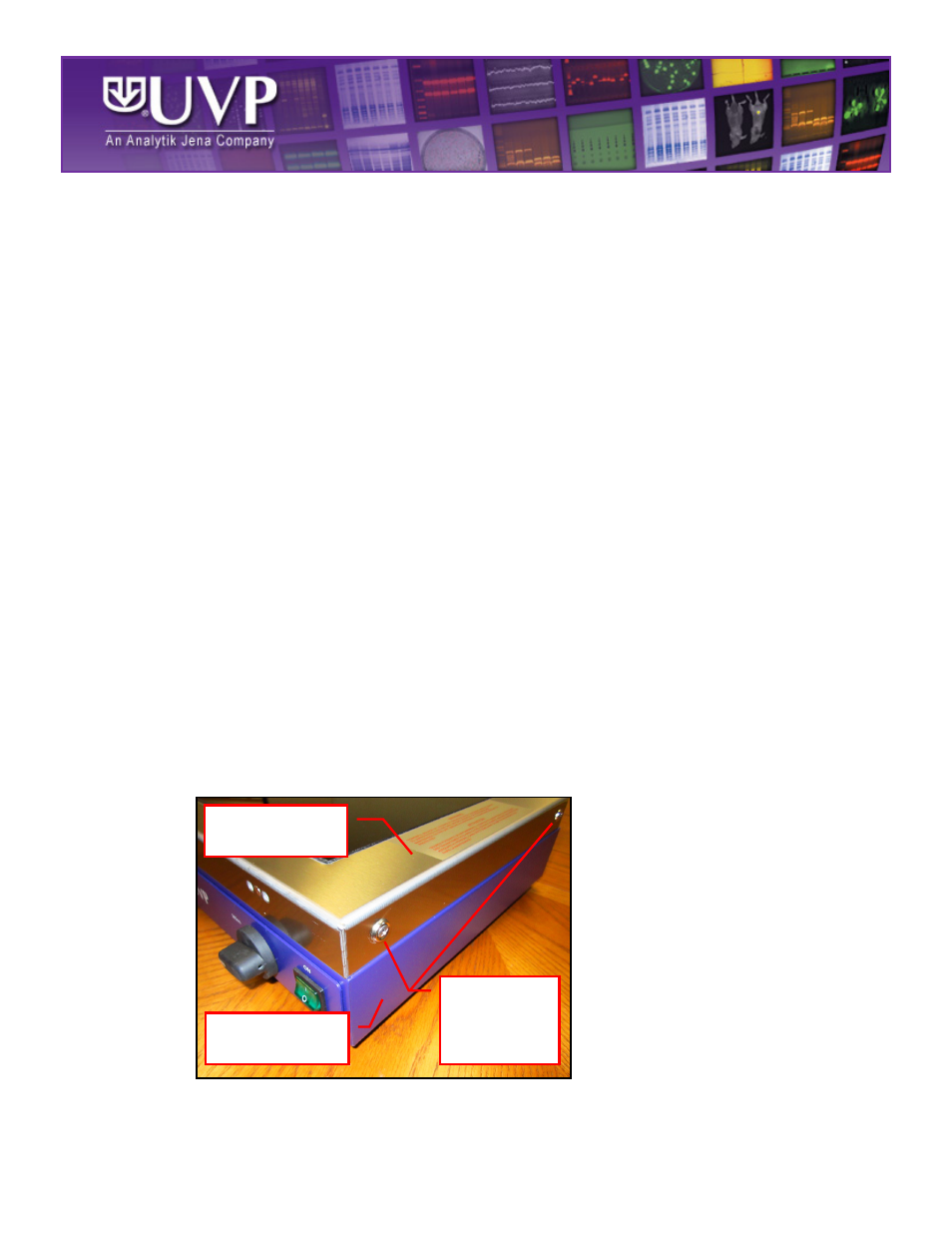
1. Turn off the transilluminator by placing the power switch on the front of the unit in the OFF
position. Then, unplug the unit from the wall power.
2. Remove the four Phillips-head screws and washers securing the transilluminator filter frame
to the body of the transilluminator. Lifting up, remove the transilluminator filter frame from the
transilluminator body and place it upside-down on a flat, smooth surface to avoid scratching
the filter glass.
Two of Four
Phillips-Head
Screws and
Washers
Transilluminator
Filter Frame
Transilluminator
Body