StorCase Technology DE300i-SW User Manual
Page 19
StorCase Technology, Inc.
DE300i-SW User's Guide - Rev. A01
12
Installation
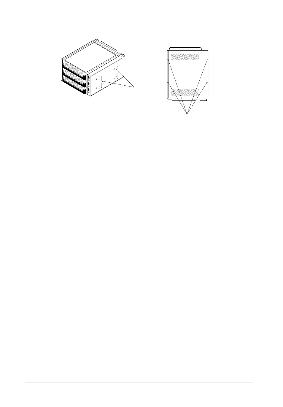
Mounting
Holes
(Right)
0520
Mounting
Holes
(Bottom)
Front of Unit
Figure 9: Receiving Frame Mounting Holes
5. Adjust the front of the receiving frame so the carrier slides freely in and out on the
receiving frame guides. The position of adjoining peripheral units may require
adjustment.
6. To connect a drive to a remote activity LED in the computer system or expansion chassis,
connect the appropriate cable(s) to the receiving frame motherboard connectors J3A,
J3B, and J3C Pins 11 & 12 as shown in Figure 5.
7. Connect the I/O cable from the host adapter to the receiving frame. The Pin 1 indicator
on the cable must be properly aligned. Refer to Figure 5 for the correct Pin 1 location.
8. When installing the DE300i-SW into a computer system, make sure that only the last SCSI
device is terminated. If the DE300i-SW is at the end of a daisy chain, the receiving frame
termination for the last device must be enabled by removing the appropriate
jumper. If the DE300i-SW is in the middle of a daisy chain, termination should be
disabled (factory installed jumper) at J3A, J3B, and J3C, Pins 9 & 10 (Figure 8).
In most cases, if installing the DE300i-SW into an external expansion chassis, the
factory-installed jumpers at J3A, J3B and J3C, Pins 9 & 10 (disable termination) should
be left in place. Termination will be handled by an external terminator on the expansion
chassis.
9. Connect the power cable from the DC power supply in the computer or expansion
chassis to the power connector on the DE300i-SW receiving frame. Refer to Figure
5 for the receiving frame power connector location.
10.
Replace any expansion boards that may have been removed earlier. Replace the
system cover according to the manufacturers instructions.
11.
Reconnect any system or peripheral cables removed earlier.