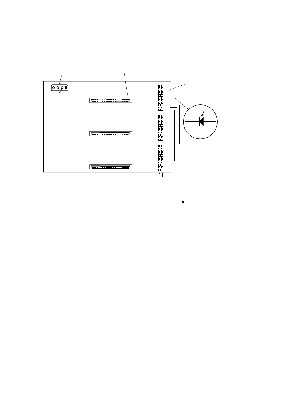
Figure 5: receiving frame mother board (rear view) – StorCase Technology DE300i-SW User Manual
Page 13
6
Introduction
StorCase Technology, Inc.
DE300i-SW User's Guide - Rev. A01
DC Power
Connector
Ground
Row
J6
+5
+12
GND
1
21
J3A
J3B
J3C
1
1
Remote ID
Select
Anode
Cathode
P11
P12
Remote
Activity LED
Disable On Board
Terminaton
(Installed
at Factory)
Wide SCSI I/O Connector (Pin 1)
J3
Signal
Row
21
21
Term. Power
To/From SCSI Bus
0503
= Pin 1
J4
J5
ID0
ID1
ID2
ID3
DT
RLED
DF
SYNC
TPWR
WTP
LK
ID0
ID1
ID2
ID3
DT
RLED
DF
SYNC
TPWR
WTP
LK
ID0
ID1
ID2
ID3
DT
RLED
DF
SYNC
TPWR
WTP
LK
Reserved
Figure 5: Receiving Frame Mother Board (Rear View)
See also other documents in the category StorCase Technology Computer Accessories:
- DE100i-SW (35 pages)
- DE50 (33 pages)
- DE50 (27 pages)
- DE110 (33 pages)
- DE110 (2 pages)
- DE110 (31 pages)
- DE110 (27 pages)
- DX115 (25 pages)
- DE75i-A (31 pages)
- DE75i-A66 (29 pages)
- DE75i-A100 (31 pages)
- SATA DE75 (28 pages)
- DE75i-S (31 pages)
- DE75i-SW (33 pages)
- DE75i-SWC (33 pages)
- DE75i-SW160 (29 pages)
- S20A114 (29 pages)
- DE75i-SWC160 (29 pages)
- DE90i-A (29 pages)
- DE90i-A66 (23 pages)
- DE90i-A100 (23 pages)
- DE90i-S (25 pages)
- DE100i-A (33 pages)
- DE100i-A66 (29 pages)
- DE100i-A100 (29 pages)
- DE100i-CSWTN (2 pages)
- DE100i-S (39 pages)
- DE100i-SWD (33 pages)
- DE100i-SWU2 (37 pages)
- DE100i-SWCU2 (33 pages)
- DE100i-SWU2X (35 pages)
- DE100i-SW160 (35 pages)
- S20A102 (33 pages)
- DE100i-SWC160 (39 pages)
- Ultra320 DE100 (31 pages)
- DE110 (27 pages)
- DE110 (31 pages)
- DE110 (29 pages)
- DE150i-SWC (33 pages)
- DE200i-S (33 pages)
- DE200i-CSWTN (2 pages)
- DE200i-SW (35 pages)
- DE200i-SWU2 (37 pages)
- DE200i-SWCU2 (35 pages)
- S20A108 (33 pages)