StorCase Technology DE150i-SWC User Manual
Page 26
DE150i-SWC User's Guide - Rev. B00
StorCase Technology, Inc.
Appendix B - Factory-Installed Options
19
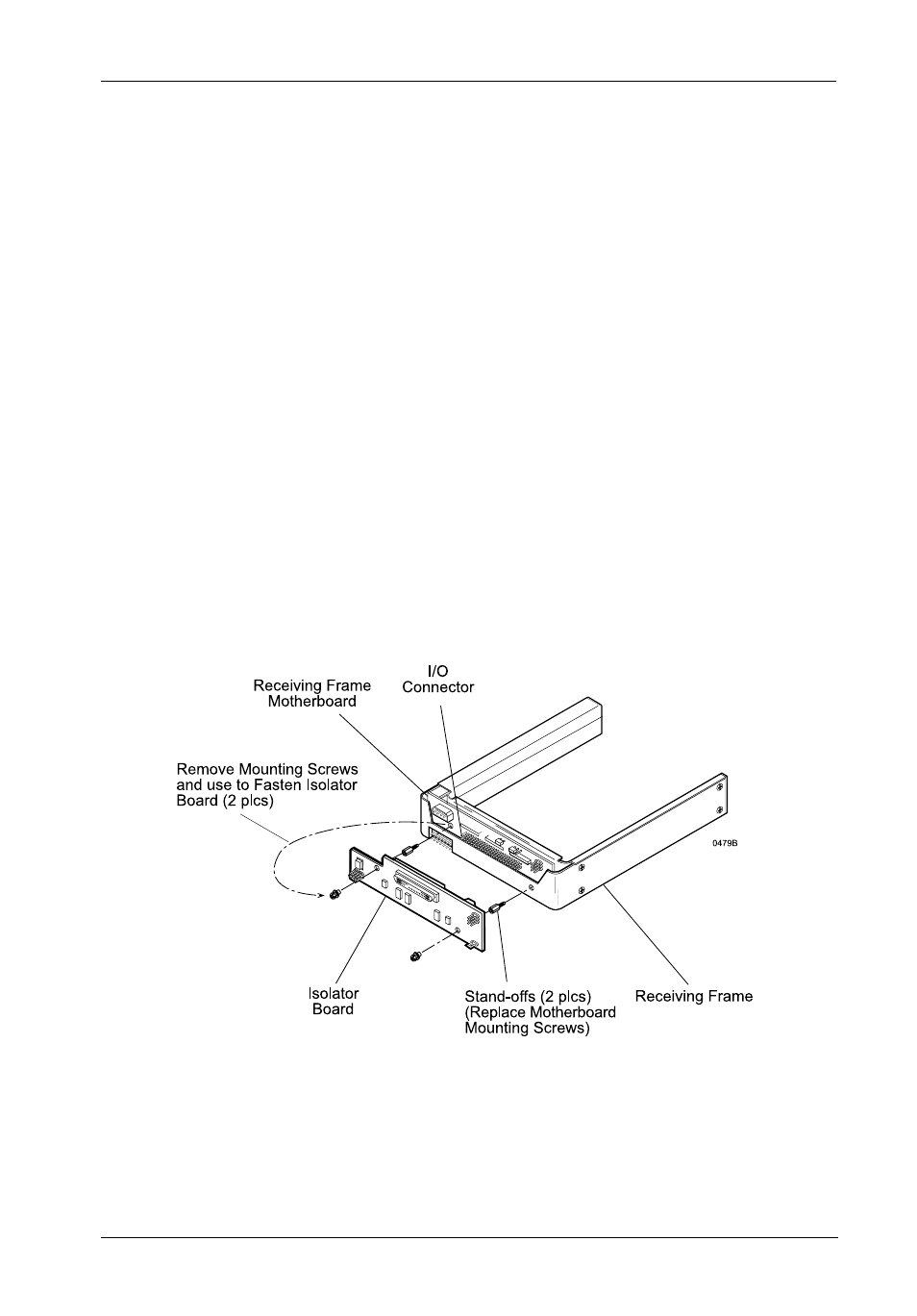
Figure B-1: Attaching the Isolator Board
1. Remove the two (2) Phillips head machine screws from the receiving frame motherboard
and set the screws aside (Figure B-1).
2. Remove jumpers on the receiving frame motherboard locations J4 - Pins 7 & 8, and
J6 - Pins 1 & 2 (Figure 7). Also make sure that W2 is set to Position "A" (default setting)
to disable onboard termination from the receiving frame motherboard.
3. Attach the two (2) provided stand-offs into the receiving frame motherboard holes in
place of the two removed screws. Carefully align the connectors of the Isolator Board
with the connectors on the receiving frame board and gently push the board into
position. Make certain that all connectors are properly mated.
4. Attach the Isolator Board to the receiving frame motherboard by using the two screws
removed earlier and insert them through the board into the stand-offs.