Receiving frame rear panel – StorCase Technology DE150i-SWC User Manual
Page 12
Introduction
5
DE150i-SWC User's Guide - Rev. B00
StorCase Technology, Inc.
Receiving Frame Rear Panel
I/O Connector (J2): The input/output connector provides a standard 68-pin Wide
interface for all SCSI signals.
DC Power Connector (J3): The DE150i-SWC uses a standard 4-pin DC Power
Connector to accept DC power.
ID Select Pins (J4): Pins 1-14 are reserved. Pins 15 through 20 of this connector
provide unit SCSI ID selection for the computer system or expansion chassis. For
remote ID selection through an expansion chassis, the unit ID must be set to "0" or
open (no jumpers installed) on these pins. See Table 1 for J4 pin as-signments.
Enable Termination Power To/From SCSI BUS (W1): This jumper is installed
at the factory.
Onboard Termination Resistors (W2): Position "A" is installed at the factory and
will disable termination. Moving the jumper to Position "B" will enable onboard
termination.
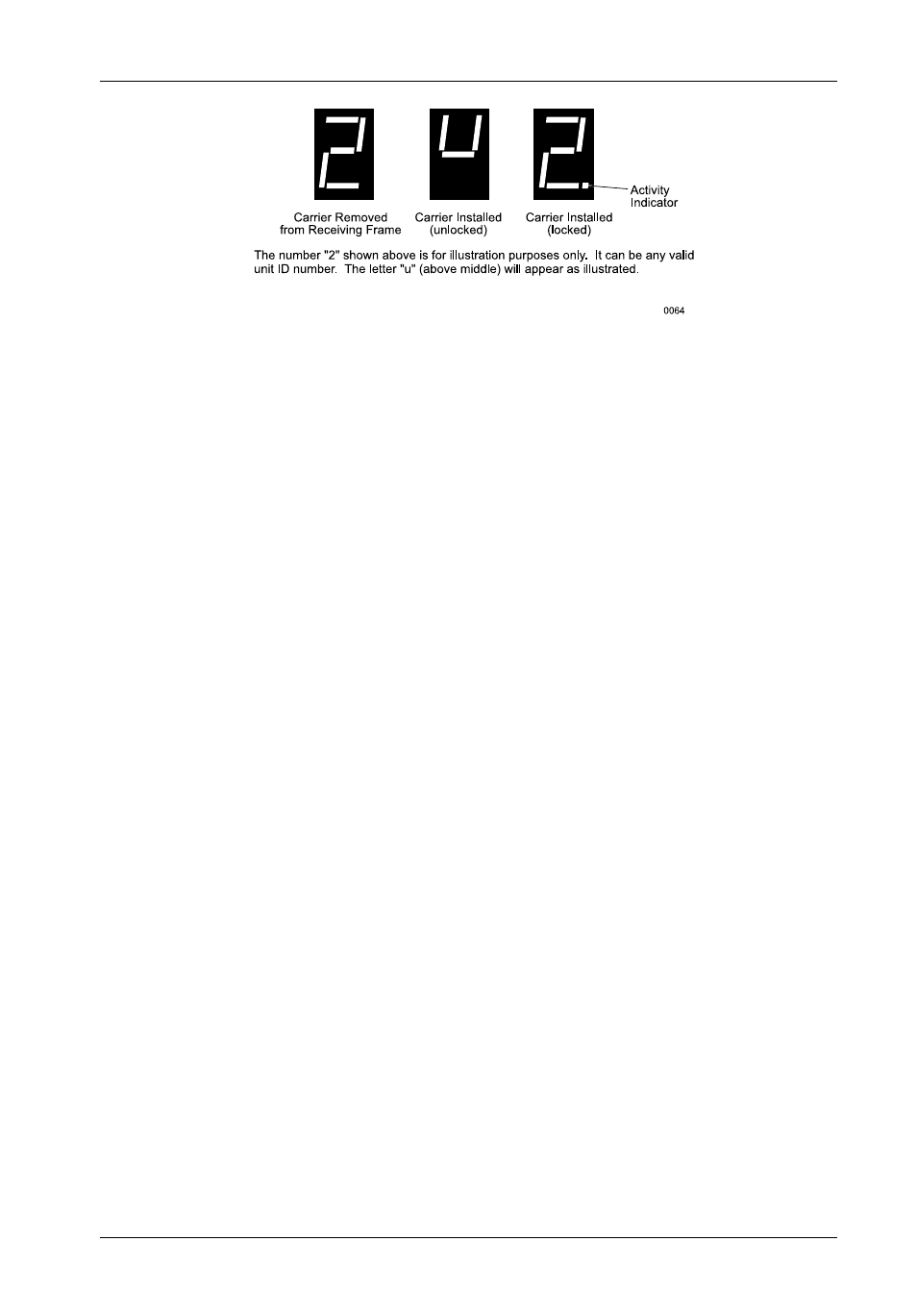
Figure 4: Receiving Frame Unit ID Number and Activity Display