StorCase Technology DE150i-SWC User Manual
Page 16
DE150i-SWC User's Guide - Rev. B00
StorCase Technology, Inc.
Installation
9
IMPORTANT NOTE: In order to use remote ID selection from a computer or expansion
chassis, the Unit ID number on the DE150i-SWC receiving frame
must be set to "0" with the provided alignment tool. Refer to the
section "Selecting the Unit ID Number" later in this User's Guide
for the Unit ID selection procedure.
4.
With the drive carrier locked in place inside the receiving frame, install the DE150i-
SWC into the 5.25 drive opening in the computer or expansion chassis. Use the
appropriate guides to position the DE150i-SWC, and fasten it into place with the
four (4) #6-32 Phillips screws provided. Figure 8 illustrates the location of the
mounting holes. Mounting holes are provided on each side and the bottom of the
receiving frame to accommodate a variety of mounting configurations. Use the
mounting holes which best suit the computer or expansion chassis configuration.
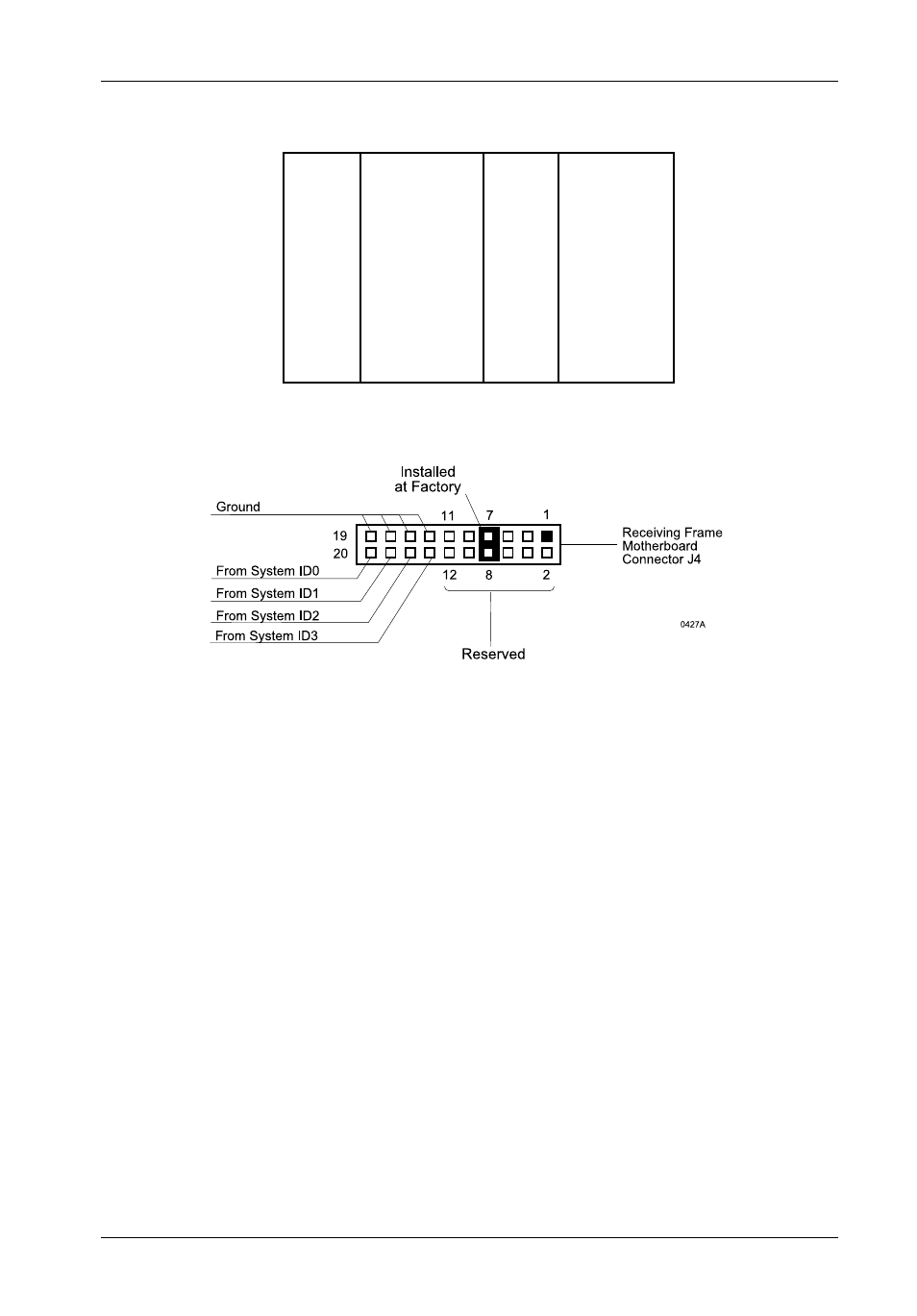
Figure 7: Receiving Frame Connector J4 Pin Configuration
Table 1: Receiving Frame Motherboard Connector J4 Pin Configuration
Pin 1
RESERVED
Pin 11
RESERVED
Pin 2
RESERVED
Pin 12
RESERVED
Pin 3
RESERVED
Pin 13
Ground
Pin 4
RESERVED
Pin 14
ID3
Pin 5
RESERVED
Pin 15
Ground
Pin 6
RESERVED
Pin 16
ID2
Pin 7
RESERVED
Pin 17
Ground
Pin 8
RESERVED
Pin 18
ID1
Pin 9
RESERVED
Pin 19
Ground
Pin 10
RESERVED
Pin 20
ID0