StorCase Technology DE150i-SWC User Manual
Page 17
StorCase Technology, Inc.
DE150i-SWC User's Guide - Rev. B00
10
Installation
5.
Adjust the front of the receiving frame so the carrier slides freely in and out on
the receiving frame guides. The position of adjoining peripheral units may require
adjustment.
6.
To connect the drive to a Remote Activity LED in the computer system or
expansion chassis, connect the appropriate cable(s) to the receiving frame
motherboard as shown in Figure 5. Connect J6 Pins 4 and 6 to a remote activity
LED.
7.
Connect the I/O cable from the host adapter to the receiving frame. The Pin 1
indicator on the cable must be properly aligned. Refer to Figure 5 for the correct
Pin 1 location.
Make sure that only the last SCSI device is terminated. If the DE150i-SWC is at
the end of a daisy chain, the terminators on the receiving frame must be enabled.
If the DE150i-SWC is in the middle of a daisy chain, termination should be disabled.
Refer to jumper W2 in Figure 5.
8.
Connect the power cable from the DC power supply in the computer or expansion
chassis to the power connector on the DE150i-SWC receiving frame. Refer to
Figure 5 for the DE150i-SWC receiving frame power connector location.
9.
Replace any expansion boards that may have been removed earlier. Replace
the system cover according to the manufacturers instructions.
10.
Reconnect any system or peripheral cables removed earlier.
11.
Turn ON power to the computer. If the installation has been successful, and all
cables have been properly attached, the system should boot normally. Although
the computer may not recognize the DE150i-SWC yet, the appropriate front panel
LED indicators should illuminate.
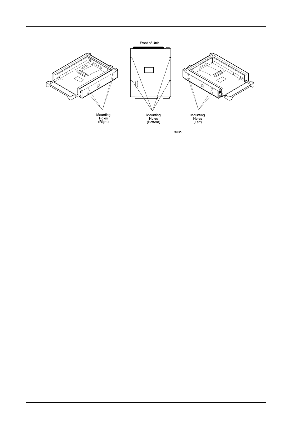
Figure 8: Receiving Frame Mounting Holes