Spacer plates (optional) – StorCase Technology DE110 User Manual
Page 18
PATA DE110 User's Guide - Rev. C03 StorCase Technology, Inc.
Installation
11
5.
Connect the I/O cable from the host adapter to the receiving frame. The Pin 1 indicator
on the cable must be properly aligned. Refer to Figure 5 for the correct Pin 1 location.
6.
Connect the power cable from the DC power supply in the computer or expansion
chassis to the power connector on the DE110 receiving frame. Refer to Figure 5
for the DE110 receiving frame power connector location.
7.
Replace any expansion boards that may have been removed earlier. Replace the
system cover according to the manufacturers instructions.
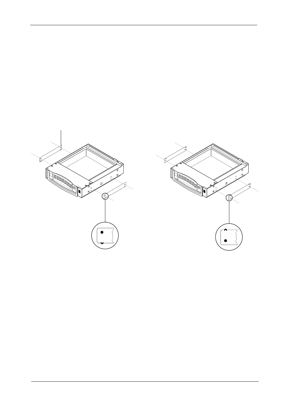
Spacer Plates (Optional)
NOTE:
Depending on the computer system, spacer plates may be positioned on the
receiving frame to utilize either top or bottom row of side-mounting holes
(Figure 8B).
The DE110 is designed to fit most computer systems with standard 5.25" peripheral slots.
The installation of the spacer plates (provided) may or may not be necessary.
Figure 8B: Spacer Plate Installation (Optional)
Spacer Plate
(2 Total)
OR
0869