Receiving frame rear panel – StorCase Technology DE110 User Manual
Page 13
6
Introduction
StorCase Technology, Inc.
PATA DE110 User's Guide - Rev. C03
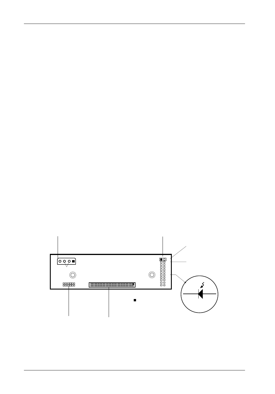
Figure 5: Receiving Frame Motherboard
(Rear View)
DC Power
Connector
(P1)
P1
+5
+12
GND
1
2
Master Drive
Select (ID0)
(Factory-Installed
Jumper)
Cathode
Anode
P13
P14
Remote
Activity LED
I/O Connector
(JP1)
JP1
0839
= Pin 1
W1
Option Pin
Connector
(W1)
13
14
Slave Drive
Select (ID1)
3
4
Factory Reserved Pins
(No Jumper Installed)
Receiving Frame Rear Panel
(Figure 5)
I/O Connector (JP1) - The input/output connector provides a standard interface for all
IDE signals (Figure 5).
DC Power Connector (P1) - A standard 4-pin DC power connector is used to accept
DC power.
Option Pins (W1)
Master/Slave Selection Jumper (ID0 & ID1) - Master Drive designation (jumper is
factory-installed on ID0). Change jumper position to Pins 3 & 4 (ID1) for Slave Drive
designation.
Forces Master/Slave Drive configuration on the receiving frame, if jumper option on the
drive itself is configured for Cable Selection (recommended configuration). Refer to
page 7 for further information.
If using the Drive Select Method, this option is instead used to configure the unit ID display
only (refer to page 7 for further information).
Remote Activity LED (RLED) - These pins provide power for a remote LED device
activity indicator (Pin 13=Cathode, Pin 14=Anode).
Factory Reserved Pins - These pins are reserved for factory use only - Do not install
jumper under any circumstances!