Programming, Pattern programming – Star Headlight & Lantern ULB18 Lineum Dual-Color Half-Phanto Interior LED Lightbar User Manual
Page 6
-5-
Programming
Programming is optional. If the default settings
are acceptable, skip to the Operation section.
If you will be changing any of the options on your lightbar, this should be done prior to
installation. Programmable features include the following:
Pattern Selection
Phase Selection (which heads alternate)
Head Enable (which heads activate)
Dim Option (High-Low)
Program Mode (Copying all
settings from one light to
another)
Traffic Director /Takedown
DO NOT TOUCH THIS SWITCH !!!
This DIP switch option is only used for the full size Phantoms. Please leave this switch in
the Takedown Position.
ON
CTS
1
2
3
P
ro
g
ra
m
M
o
d
e
Hig
h
-L
o
w/
P
at
te
rn
T
ra
ff
ic
Dir
e
ct
o
r/
T
ak
e
d
o
wn
P
h
a
s
e
P
ro
g
ra
m
m
in
g
Hea
d
E
n
a
b
le
P
ro
g
ra
m
m
in
g
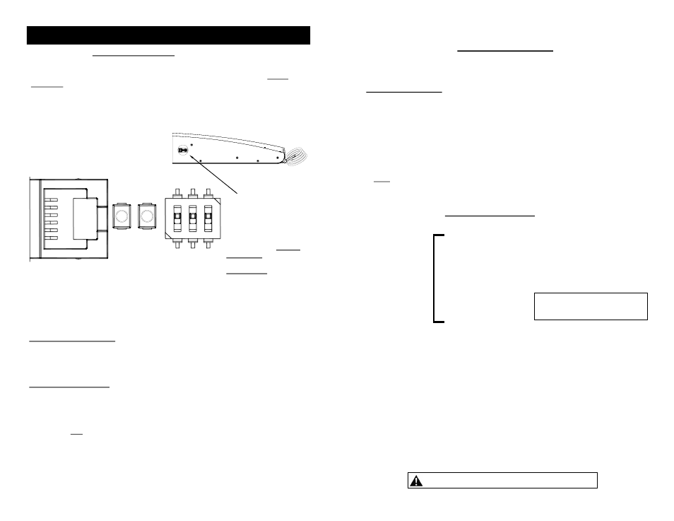
Communication Port
There are three DIP
switches, two push-button
switches, and a telephone-
style jack, all located on
the top of the light, that
should be used to set any
of these options prior to
installation.
Please Note: A small
black adhesive-backed
plastic plate (P30019-148 )
is included to cover the
opening once all
programming has been
completed.
High-Low/Pattern Option
This light is equipped with an option allowing you to dim the light for nighttime operation. If
you do not need this feature, skip this section.
The High-Low/Pattern Option switch is used to control the function of the Green w/Red wire.
The Green w/Red wire is normally used for Pattern Programming (see next page). If you
are using the Dim feature, AFTER PROGRAMMING YOUR FLASH PATTERNS, flip this
switch into the ON position (DOWN in the diagram above). When +12VDC is applied to the
Green w/Red wire, the light will dim.
-6-
Programming (CONT'D)
Pattern Programming
Not only does this light have several Patterns to select from, but it also incorporates
advanced programming that allows you to select which heads flash On and Off with one
another (Phase), and which heads are active in any of the functions (Head Enable).
Patterns for Warning Lights
(Level 1, Level 2, and Pursuit)
1 Flicker *
2 Slow Singleflash
3 Fast Singleflash
4 Slow Doubleflash
5 Fast Doubleflash
6 Slow Tripleflash
7 Fast Tripleflash
(Level 2 default)
8 Quadflash
9 Quintflash
10 Tripleflash w/Post Pop
11 Quadflash w/Post Pop
12 Quintflash w/Pre Pop
13 Singleflash Flicker **
14 Doubleflash Flicker
15 Single, Quad w/Post Pop, Flicker
16 Delta-Omega
17 Moving Delta-Omega ***
18 Random 1
19 Random 2
20 Random 3
21 Flashing Bounce
22 Full Bounce
(Level 1 default)
23 Split Bounce
24 Half Bounce
25 Bounce w/End Pop
26 Search Lights
27 Eyeballz
28 Fade Invert
29 Singleflash w/Alternating Ends
30 Triple In/Triple Out
31 Two Speed
(Pursuit default)
C
a
lif
or
nia
Tit
le
1
3
SAE
J
59
5 Ap
p
rov
ed
P
a
tter
ns
Basic Pattern Selection
The first step in programming is to select a basic pattern for each function:
Level 1 Warning Lights
(Orange w/Green)
Level 2 Warning Lights
(Orange w/Red)
Pursuit
(White w/Brown)
1. Connect the Red wire to power and the Black wire to Ground.
2. Activate the function you wish to program by connecting the corresponding wire to power.
3. Touch and release the Green w/Red wire to +12VDC to scroll through the patterns below.
Note: At any time you can shortcut to the patterns indicated with the asterisks by holding
the pattern select wire to +12VDC for the indicated time.
4. Repeat for each function you wish to program.
Please note: All California Title 13 and SAE J595 approved patterns need
to be configured properly to ensure compliance with those specifications.
* Shortcut Pattern #1 (3 sec/1 flash)
** Shortcut Pattern #2 (6 sec/2 flashes)
*** Shortcut Pattern #3 (9 sec/3 flashes)