Star Headlight & Lantern 7400 Star Lase User Manual
Page 5
-2-
(Wiring Instructions CONT’D)
Wire Connections
To aid with installation, the Laser lightbar utilizes two “shielded” wiring harnesses (three harnesses
for models with a traffic director). One harness contains the “control wires” and is typically run to
your switchbox, while the other harness contains the Power and Ground wires, which are typically
run to the battery.
Feature
Apply +12VDC to:
Fr. Takedowns Green w/Yellow
Rear Worklights Green w/White
Pattern Select
Red w/Green (TEMP)
Left Turn Signal Yellow
Right Turn Signal Green
Tail Lights
Brown
Feature
Connect to Ground:
Low Power
Purple
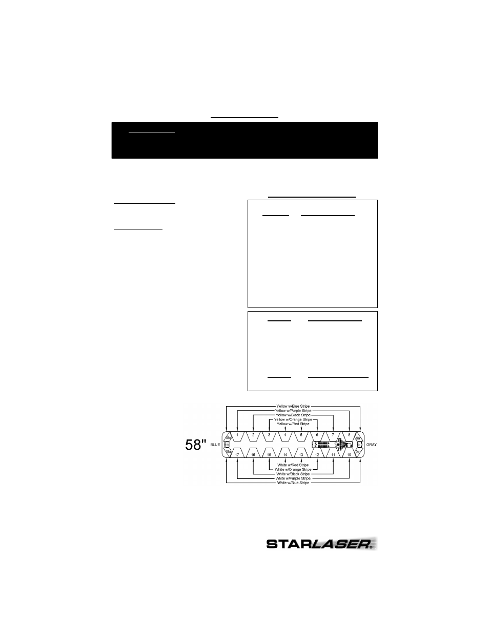
Lightbar
Location
Apply +12VDC to:
18b
Blue (Left Alley)
9b
Gray (Right Alley)
18c/9a
Yellow w/Blue Stripe
1/8
Yellow w/Purple Stripe
2/7
Yellow w/Black Stripe
3/6
Yellow w/Orange Stripe
4/5
Yellow w/Red Stripe
18a/9c
White w/Blue Stripe
10/17
White w/ Purple Stripe
11/16
White w/Black Stripe
12/15
White w/Orange Stripe
13/14
White w/Red Stripe
Control Harness Wire Colors
Control Wire Harness
The wire colors utilized in all of our Laser
lightbars will always control the light heads in a
specific location(s). Please review the diagrams
on page 4 for a complete list of wire colors used
in each different length lightbar.
•
Your Control Wire Harness will contain
all 19 of the colored wires, the drain
wire, and the foil shield. Most
applications will not use every wire.
•
The “dead” wires in the harness will be
connected to the terminal block inside
your lightbar, but if there are no heads
in the corresponding locations inside
the lightbar, then those wires will be
non-functional.
•
The “dead” wires can be used if you
wish to move the location of any of the
heads (i.e. you wish to move the
takedown lights from the center to the
outer location), or for additional
components that may be added at
some point in the future.
Connect the appropriate wires from the Control Wire Harness to your switchbox (user
provided). Whenever +12VDC is applied to any of the wires, the corresponding heads will be
activated (as long the red wire from the Power Harness is connected to +12VDC and the
black wire from the Power Harness is connected to the negative side of the battery).
PLEASE NOTE: If you need a cable longer than the existing 15-foot harnesses
supplied with the lightbar, it is recommended that you completely
replace the harness, rather than adding on to it. Please see the
Wire Harness Replacement section on pages 5-6.
Note:
The “drain” wire in
both harnesses
should be connected
to a good chassis
ground.