Ch 3, Input channel i/o connectors – Speck Electronics LiLo User Manual
Page 22
Chapter 3
Operation Section
18
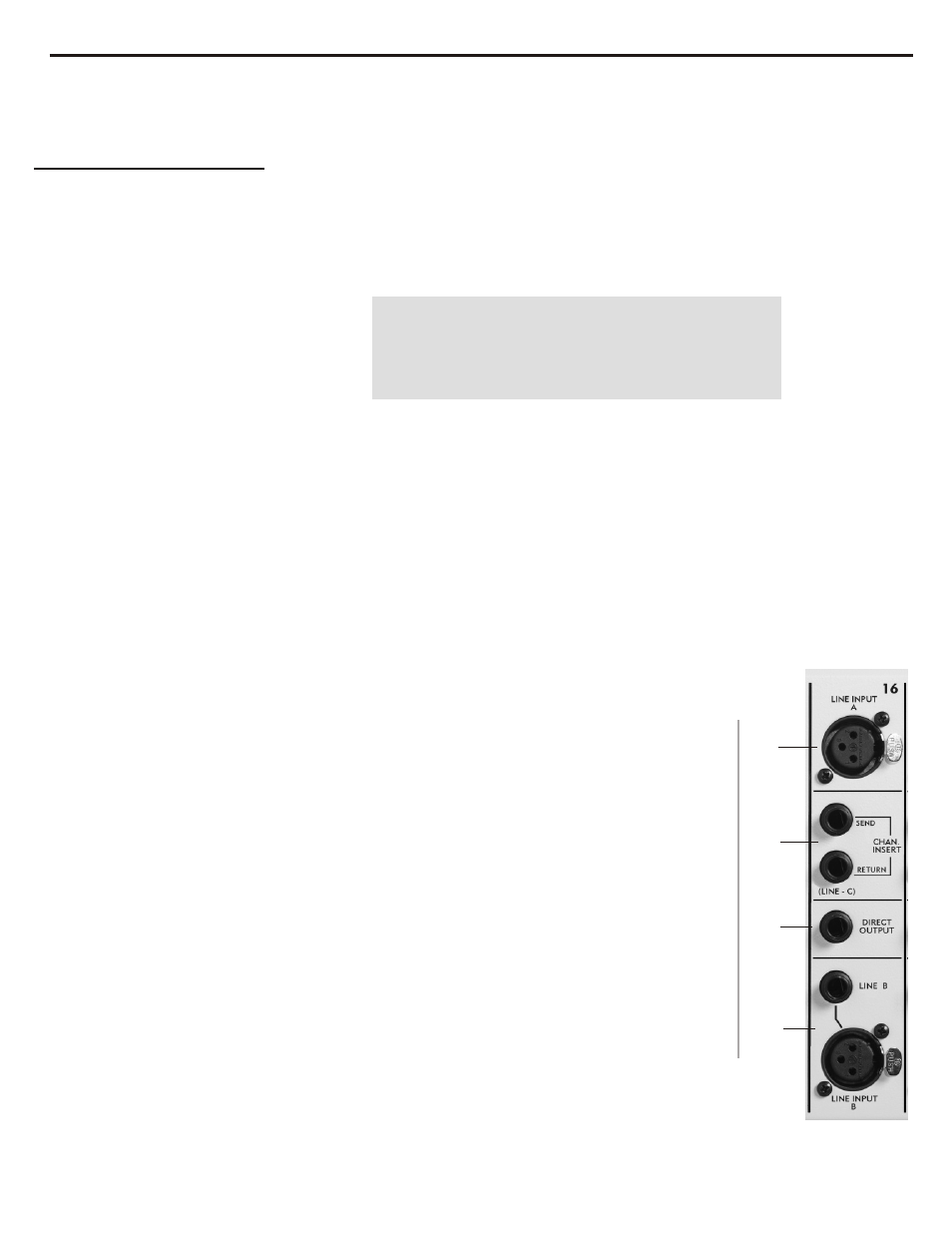
Each of the input channels has a balanced XLR Line-A input connector,
balanced XLR and TRS connectors for Line-B, balanced ¼" TRS connectors
for the Inserts, and a balanced ¼" TRS Direct Out.
This XLR active-balanced input is suitable for any high level line source.
This active-balanced input is suitable for any high level line source. The XLR
connector and ¼” TRS jack are wired in parallel.
Each input channel on the LiLo has a balanced send and return available via
separate ¼” TRS jacks. The inserts signal path is located immediately after
the Polarity switch and just before the Fader . When the channel's Insert
switch is depressed, any audio device (such as an equalizer or filter)
connected to the send/return connectors is inserted in the channel's audio path.
If the Insert switch is enabled and nothing is plugged into the
return jack, the signal will pass through because the jacks have
switching (normalling) contacts that are only broken by the
insertion of a plug. The insert send/return operates at
nominal level of +4dBu.
The insert return can also be used as a “Line-C” input by
connecting a source to the insert return jack and
depressing the Insert switch.
As an option, the input channels can be ordered with a
relay installed that will bypass the insert return electronic
circuitry when not in use. The active-balanced return
circuitry will only be activated when a plug is inserted
into the return jack.
The Direct Output provides an active-balanced line level
signal from the channel and operates at a nominal level of
+4dBu. The Direct Output is ideal for minimum signal
path connection to multitrack recorder. Although the
source of the direct out is the channels fader, it can be
easily configured so the signal source is the Line-A
preamp, Line-B preamp, Aux 2 send, or Aux 4 send. See the
circuit board configuration jumpers shown in Figure 9b.
The pin configuration for all XLR connectors is:
Pin 1=Ground, Pin 2=High (+), Pin 3=Low (-)
The pin configuration for all ¼" TRS jacks is:
Tip=High (+), Ring=Low (-), Sleeve=Ground
21. Line-A Input
22. Line-B Input
23. Insert Send
and Return
24. Direct Output
Input Channel
I/O Connectors
21
23
24
22
Input Channel
Relay Option