Rear panel connections – Simaudio 700i Integrated Amplifier User Manual
Page 15
700i Reference Dual-Mono Integrated Amplifier
____________________________________________________________________________________
15
Rear Panel Connections
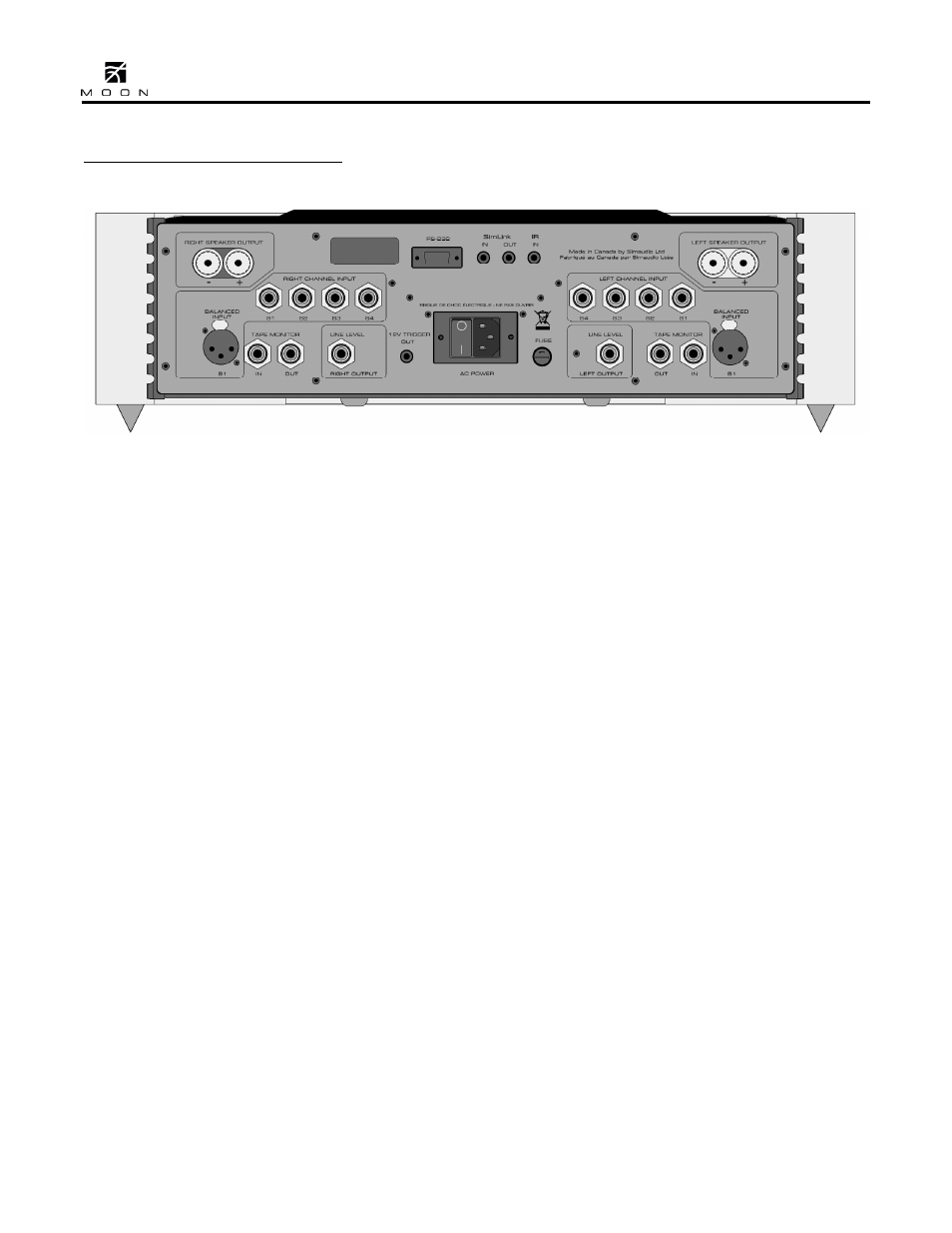
Figure 2: Rear panel of MOON 700i Integrated Amplifier
The rear panel of the MOON 700i dual-mono
integrated amplifier will look similar to Figure 2
(above). There are two rows of connectors; the top
row contains one pair of heavy duty gold-plated
speaker binding posts for each channel to connect to
your loudspeakers. This integrated amplifier is
equipped with full-function bi-directional RS-232 port
control and status for custom integration or
automation. This is located in the middle section
and uses a DB9 connector. Immediately to the right
of the RS-232 port are two (2) “SimLink” connectors
labeled “in” and “out” on 1/8” mini jacks. Please
refer to the next section entitled SimLink for more
details. As well, there’s a 1/8” mini-jack input for
use with aftermarket infrared remote control
receivers.
The middle row contains four (4) pairs of single-
ended RCA inputs labeled S1, S2, S3, and S4. As a
result of this integrated amplifier’s dual-mono
design, the left channel inputs are grouped together
on one side and the right channel inputs are
grouped together on the opposite side. Don’t
hesitate to use high quality interconnect cables. Poor
quality interconnect cables can degrade the overall
sonic performance of your system.
On the bottom row you will find one pair balanced
XLR inputs labeled B1 with each channel’s input
connector located on its respective side, just like the
single-ended inputs. Beside each of these XLR
inputs is a single-ended tape monitor loop; both the
input and output connectors for each channel are
located on their respective sides of the rear panel.
The 700i also has a line-level preamplifier output
that allows you to use this integrated amplifier only
as a preamplifier, for use with a separate power
amplifier. In the middle section is the 12V trigger
output on a 1/8” mini-jack. Immediately to the right
is the “AC Power” section with a main power switch
(“0”=off, “1”=on), IEC receptacle for the included
AC power cord and the “AC Fuse” socket cover.
All rear panel connectors have been chosen because
they provide the best possible connections for your
unit. A poor contact will degrade the signal
substantially, and plugs and sockets should all look
clean and free of dirt and corrosion. The easiest way
to clean them is to remove the cables from their
sockets and push them back in again. This
procedure requires that your integrated amplifier
and the rest of your components be completely
turned off.