Rear panel connections – Simaudio 850P Preamplifier User Manual
Page 16
850P Reference Dual-Mono Preamplifier
____________________________________________________________________________________
16
Rear Panel Connections
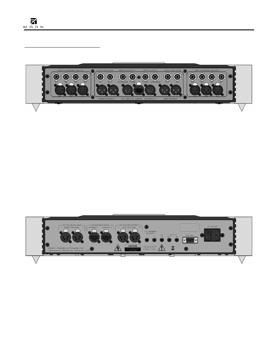
Figure 3: Rear panel of MOON 850P Preamplifier
The rear panel of the MOON 850P dual-mono
preamplifier will look similar to Figure 3 (above).
There are two rows of connectors; the top row
contains single-ended RCA inputs/outputs and the
bottom row contains balanced XLR inputs/outputs,
as well as the three input connections from the
separate digital controller chassis. There are three
(3) pairs of balanced inputs on XLR connectors (B1,
B2, B3) and four pairs (4) of single-ended inputs on
RCA connectors (S1, S2, S3, S4). As a result of this
preamplifier’s dual-mono design, the left channel
inputs are located on the left side and the right
channel inputs are locted on the right side. This
preamplifier is also equipped with a single-ended
monitor loop; the input and output connectors for
each channel are located on their respective sides of
the rear panel. The 850P has two (2) pairs each of
balanced outputs and single-ended outputs. Both
balanced outputs are variable; One single-ended
output is variable and the other one is fixed,
meaning that it bypasses the volume control. Don’t
hesitate to use high quality interconnect cables. Poor
quality interconnect cables can degrade the overall
sonic performance of your system.
Figure 4: Rear panel of MOON 850P Controller
The rear panel of the MOON 850P controller will
look similar to Figure 4 (above). It is equipped with
full-function bi-directional RS-232 port control and
status for custom integration or automation. This is
located in the upper-middle section and uses a DB9
connector. Immediately to the right of the RS-232
port are two (2) “SimLink” connectors labeled “in”
and “out” on 1/8” mini jacks. Please refer to the
next section entitled SimLink for more details. Your
MOON 850P preamplifier has a 1/8” mini jack input
for use with aftermarket infrared remote control
receivers. The “IR in” connector is located on the
upper right section of the rear panel. Across the
lower section you will find the 3 pairs of output
connectors that are used for powering the
preamplifier chassis. To the right of these