Hp remote sense, Sensesense – Remy 36SI ALTERNATOR User Manual
Page 2
NOTICE
- Only licensed Remy International, Inc. product and component parts should be used, and the use of other parts or modifications not approved
by Remy International, Inc. will void all applicable warranties. The failure to carefully follow these Installation Instructions, set forth above, will void all
applicable warranties. DELCO REMY is a registered trademark of General Motors Corporation, licensed to Remy International, Inc. Pendleton, IN 46064.
©
2012 Remy International, Inc. All rights reserved
2
Technical support: USA 800 854 0076, Mexico 01 800 000 7378, Brazil 0800 703 3526, South America 55 11 2106 6510 or visit
delcoremy.com
GROUND SCREW (-)
[LOCATION WILL VARY]
5.6-6.8 Nm (50-60 lb in)
33SI, 34SI, 35SI, & 36SI
HP REMOTE
SENSE
™
SENSESENSE
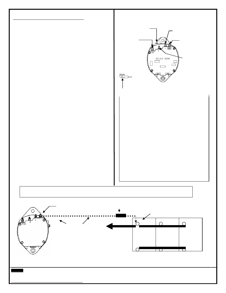
TERMINAL DESCRIPTIONS (See illustrations):
“POS” Terminal - Output terminal connects to the
positive (+) battery terminal.
“R” Terminal - Relay terminal carries half systems voltage and
may be used for certain types of control relays, charge indicators,
tachometers or similar devices. The current draw should not
exceed four (4) amperes. Notice! Do not install the remote
sense lead to this terminal.
“I” Terminal - Indicator lamp/Ignition terminal carries full system
voltage. Current draw should not exceed one (1) ampere. It is
recommended current is not drawn from this terminal.
Ground Screw
– Ground lead ensures alternator is grounded. A
Ground lead is strongly recommended for optimum performance.
“Remote Sense” Terminal - Monitors batteries system voltage at
the batteries or the common distribution point. The sense terminal
on the 33SI, 34SI & 35SI & 36SI is the fourth terminal and is
identified with a “remote sense” label on the back cover plate.
If installing a remote sense alternator in a vehicle that does not
have a sense line, connect a lead, with a 5 ampere fused
link, from the voltage sense terminal to the positive (+) battery
terminal or the common distribution point at the starter solenoid
battery (+) terminal. See diagram below.
If installing a non-remote sense alternator in a vehicle that has
a remote sense line, disconnect and secure the wire from the
battery. Notice! Be careful not to ground the leads open end and if
it has a fuse it should be deactivated.
Only connect the remote sense line to the remote sense
terminal.
The “R” Terminal is Not the Remote Sense Terminal!
NOTE: Output voltage can be lowered, if necessary, on
34SI, 35SI & 36SI alternators by installing a jumper wire
between the remote sense and battery (+) terminals when a
remote sense line is not used. Use an 18 AWG minimum
wire size terminated with ring terminals to fit. Securely crimp
and solder the connections
.
OUTPUT (+)
6.2-7.9 Nm
(55-70 lb in)
REMOTE SENSE
(OPTIONAL)
1.7-2.8 Nm
(15-25 lb in)
INDICATOR/IGNITION
1.7-2.8 Nm (15-25 lb in)
RELAY
1.7-2.8 Nm
(15-25 lb in)
ADDING A REMOTE SENSE LINE
Delco Remy strongly recommends taking advantage
of remote sense technology.
Remote Sense technology allows for a more
complete battery charge and can result in extended
battery life.
ITEMS NEEDED
-
5 Amp Inline Fuse (Sealed)
-
16 or 14 Gauge wire (depending on length)
-
Ring terminals to fit Remote Sense terminal and
Battery Positive terminal.
-
Convoluted tubing anywhere wire passes metal.
NOTE: The fuse and convoluted tubing is to protect the
vehicle from the wire rubbing through to ground.
-
RELAY PIN TERMINAL MATING CONNECTOR - OBTAIN FROM
DELPHI OR OTHER APPROVED SOURCE IF REQUIRED.
ADDING REMOTE SENSE TO A VEHICLE THAT DID NOT COME WITH A REMOTE SENSE WIRE
FROM THE FACTORY
REMOTE SENSE
™
TERMINAL
MAIN POSITIVE
CABLE TO
STARTER
+
NEW WIRE
Under 10 Feet
use 16 Gauge.
Over 10 Feet use
14 Gauge
-
INLINE FUSE 5 AMP
AND CLOSE TO BATTERY
CONNECT TO MAIN
BATTERY TERMINAL
ONLY