Remy 24SI™ ALTERNATOR User Manual
Available options, 24si, Alternator installation instructions
Instruction Sheet
10524919
04OC13 REV2
NOTICE
- Only licensed Remy International, Inc. product and component parts should be used, and the use of other parts or modifications not approved
by Remy International, Inc. will void all applicable warranties. The failure to carefully follow these Installation Instructions, set forth above, will void all
applicable warranties. DELCO REMY is a registered trademark of General Motors Corporation, licensed to Remy International, Inc. Pendleton, IN 46064.
©
2012 Remy International, Inc. All rights reserved
1
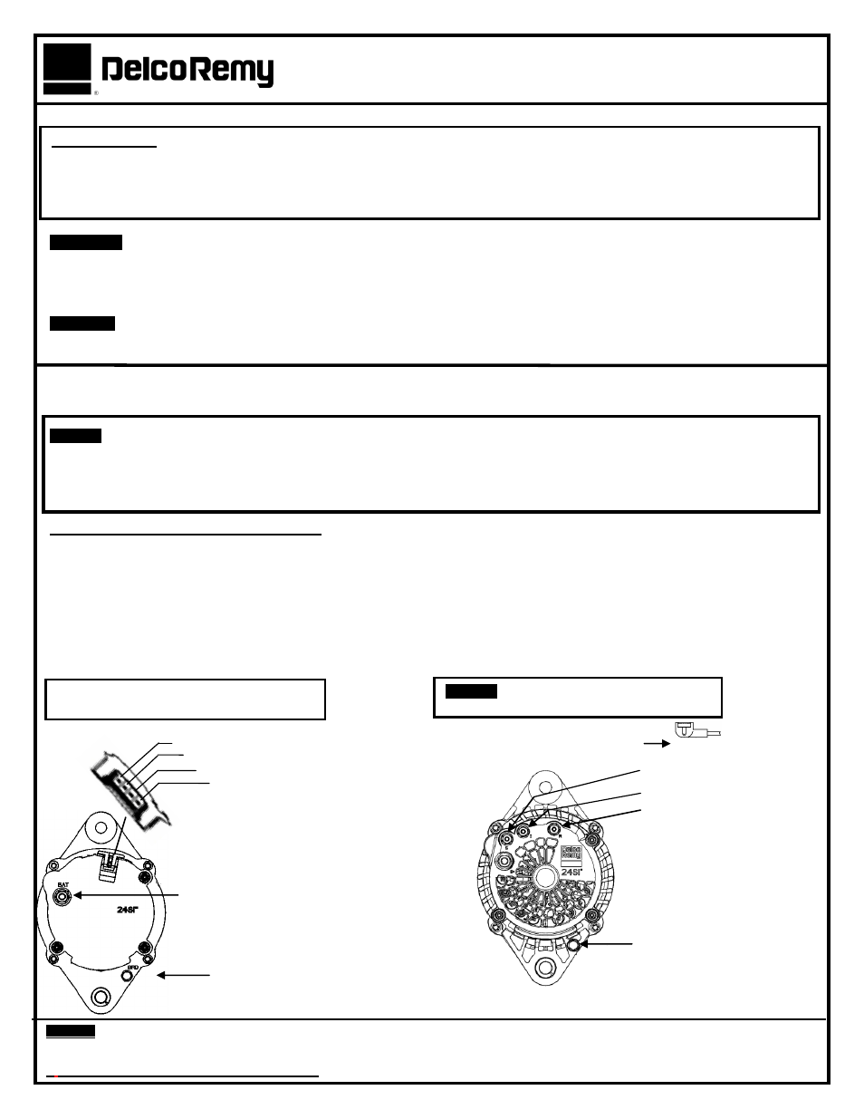
PHASE (RELAY)
INDICATOR LAMP
EXTERNAL FIELD MONITOR
REMOTE SENSE
(OPTIONAL)
GROUND SCREW
5.6-6.8 N-m (50-60 lb in)
GROUND SCREW (-)
5.6-6.8 N-m (50-60 lb in)
24SI
™
ALTERNATOR INSTALLATION INSTRUCTIONS
WARNING!!!!
ALWAYS USE PROPER EYE PROTECTION WHEN PERFORMING ANY MECHANICAL REPAIRS TO A VEHICLE
-INCLUDING, BUT NOT LIMITED TO, ANY INSTALLATION AND OR REPAIRS TO THE DELCO REMY
®
ALTERNATORS. FAILURE
TO USE PROPER EYE PROTECTION CAN LEAD TO SERIOUS AND PERMANENT EYE DAMAGE.
Only perform the mechanical functions that you are properly qualified to perform. Mechanical repairs that are beyond your te chnical
capabilities should be handled by a professional installation specialist.
DANGER!!!
To avoid injury or damage, always disconnect the negative cable at the battery before removing or replacing the alternator.
The alternator output terminal is always live (“hot”). If the battery is not disconnected, a tool accidentally touching this terminal and
ground can quickly get hot enough to burn skin or damage tools and surrounding parts.
FOLLOW ENGINE OR VEHICLE MANUFACTURER’S INSTRUCTIONS FOR REMOVING THE OLD ALTERNATOR FROM THE
ENGINE AND INSTALLING THE NEW ALTERNATOR.
NOTICE!
This is an extremely high output Alternator. Always ensure your application is equipped with the appropriate size and gauge
of cable. CHARGING LINE CABLE VOLTAGE DROP SHOULD NOT EXCEED 0.5 VOLTS (12V system), 1.0 Volts (24V system)
(ALTERNATOR OUTPUT [B+] TERMINAL TO BATTERY POSITIVE TERMINAL AT FULL OUTPUT). FOR OBTAINING ADDITIONAL
WIRING INSTALLATION INFORMATION, SEE HEAVY DUTY APPLICATION MANUALS OR CONTACT A REMY INC.
REPRESENTATIVE.
REMOVAL & INSTALLATION INSTRUCTIONS
Disconnect the negative (-) cable at the batteries.
Identify and tag all leads when removing the old alternator and install them on the same terminals of the new alternator.
Insure all leads are reconnected or contained where they cannot ground.
Torque all fasteners to values labeled in Figures 1 & 2 below.
This alternator may have more terminals than the one being replaced had or used. It will charge properly with only the battery and
ground leads connected. Use of the other terminals is optional based on need.
See “TERMINAL DESCRIPTIONS” in figures 1, 2, 3 & 4,
pages 1 & 2.
24SI
™
FEATURES
HIGH OUTPUT: 12V - 100,135,145,160 Ampere Ratings
REMOTE SENSE
™
TECHNOLOGY (AVAILABLE)
24V - 70, 100 Ampere Ratings
CONNECTION: Three (3)
available options
TWO MOUNTING OPTIONS: Pad & Delco Remy
®
Standard Hinge 198mm (7.8 inch)
BATTERY ISOLATOR BULLETIN AVAILABLE
USE PULLEY FROM OLD ALTERNATOR
(SEE PULLEY INSTRUCTIONS PAGE 2
NOTICE!
DO NOT INSTALL AN EXTERNAL
FAN ON A 24SI ALTERNATOR
BATTERY (+)
9.0-13.0 N-m
(80-120 lb in)
FIGURE 2 -
24SI™
(4 -Terminal studs & 3 -Terminal studs & Pin)
FIGURE 1 -
24SI™ (4-Pin connector)
REMOTE SENSE
™
INDICATOR/IGNITION
RELAY (Optional pin terminal)
Three (3) M5 terminals torque
3.0
–5.0 N-m (27-44 lb in)
Three (3) #10 terminals torque
1.7
–2.8 N-m (15-25 lb in)
RELAY TERMINAL CONNECTOR
– OBTAIN FROM
DELPHI OR OTHER APPROVED SOURCE
BATTERY (+)
9.0-13.0 Nm
(80-120 lb in)