Voltage regulator and receiver arming – ParkZone PKZ6680 User Manual
Page 6
EN
1
2
3
Voltage Regulator and Receiver Arming
Arming the voltage regulator also occurs after binding as previously described,
but subsequent connection of a fl ight battery requires the steps below.
CAUTION: Always disconnect the Li-Po battery from the aircraft receiver
when not fl ying to avoid over-discharging the battery. Batteries discharged to a
voltage lower than the lowest approved voltage may become damaged,
resulting in loss of performance and potential fi re when batteries are charged.
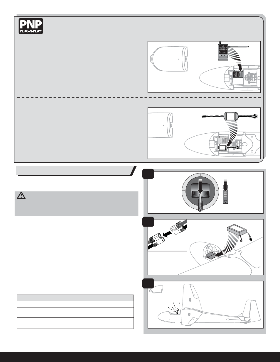
1. Power ON the transmitter and lower the throttle and throttle trim to their
lowest settings.
2. Remove the battery hatch and install the fully charged battery in the
battery compartment using the hook and loop strip, then connect the
battery to the voltage regulator.
3. When a battery is connected to the voltage regulator, the built-in battery
status LED will illuminate.
Failsafe
Failsafe positions are established when you bind your transmitter and receiver.
If radio signal connection is lost between the transmitter and receiver, the re-
ceiver immediately moves the control surfaces to the failsafe positions. Before
fl ight, ALWAYS confi rm the failsafe functions as you expect.
LED Battery Indicator
LED STATUS
2-CELL Li-Po
Solid
Battery is charged above 7.6V
Flashing
Recommend charging before fl ying
Battery is between 6.6 and 7.6V
No LED
(connected battery)
DO NOT FLY BEFORE CHARGING
Battery is below 6.6V
Monitor your aircraft battery’s voltage before and after fl ying by using a Li-Po
Cell Voltage Checker (EFLA111, sold separately).
Receiver Selection and Installation
• Before installing the wing, install your full range receiver in the fuselage
using hook and loop tape or double-sided servo tape.
• Connect the elevator and rudder servo to the appropriate channels of the
receiver.
• Connect the aileron Y-harness to the aileron channel of the receiver.
• Connect the voltage regulator to the AUX 1 channel of the receiver prior to
binding. Once bound, move the regulator to the BND port.
• Connect the spoiler extension into the throttle channel of the receiver.
Voltage Regulator Selection and Installation
Only use a voltage regulator or BEC with a 5–6 volt output. We recommend the
E-fl ite battery (EFLB13002S20) and voltage regulator (EFLA120).
• Install the voltage regulator in the fuselage using hook and loop tape or
double-sided servo tape.
• Secure the battery in the fuselage with hook and loop tape.
• Insert the power output connector from the regulator into the AUX 1
channel of your receiver prior to binding. Once bound, move the regulator
to the BND port.
• To power on the receiver, connect a battery to the voltage regulator.
Always unplug the battery from the voltage regulator when the aircraft is
not in use.
6