Wireless edge – MTI Wireless Edge MT-120018/A User Manual
Page 3
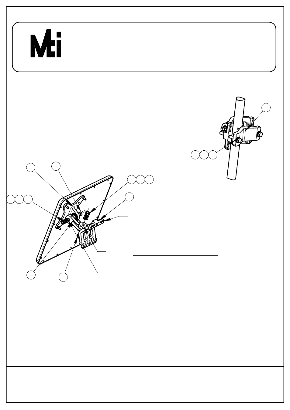
Connect base bracket as shown on page 2
Connect item 5 to item 1 (mate the knurled
surfaces) using items 6,7,8,9 as shown.
Note: the bolt head shall be positioned in the
socket of item 1.
mount item 10 on the wall on the desired position.
(note the azimuth axis oriantation)
Attach item 5 to the arm bracket item 10 (mate the
knureld surfaces) using items 6,7,8,9 as
shown. Note the bolt head shall be positioned
in the socket of item 5.
Use tightening torque of 24 N/m to the azimuth
and elevation hardware.
MOUNTING ON A WALL
1
5
10
9
8
7
6
6
7
8
9
Wall mounting
holes ( Hardware
not supplied)
Elevation
axis
Azimuth
axis
STEP 2 (FOR POLES SIZES 1"-1.75")
Install the antenna to the pole using
item 11 as shown, tighten the bracket
using items 8,9,12.
Use tightening torque of 14N/m.
11
8
9
12
x2 x2 x2
WIRELESS EDGE
SHEET 4 OF 4
RD42661500C/REV-A
11 Hamelacha St. , Afek Industrial Park, Rosh Ha’ayin 48091, Israel
Fax: 972-3-9008901, Tel: 972-3-9008900
www.mtiwe.com