Livorsi DTS Controls User Manual
Page 4
Livorsi DTS Controls- Three/Four Engine Installation
APRIL 2012
Page 4 of 9
Livorsi DTS Control Dimension Chart
Number of Handles
“A” DIM
“B” DIM
3 handle
4- 1/2 in.
4- 1/64 in.
4 handle
5- 11/16 in.
5- 3/16 in.
6 handle
8 in.
7- 1/2 in.
8 handle
10- 5/16 in.
9- 13/16 in.
Installing the Control
Control Configuration
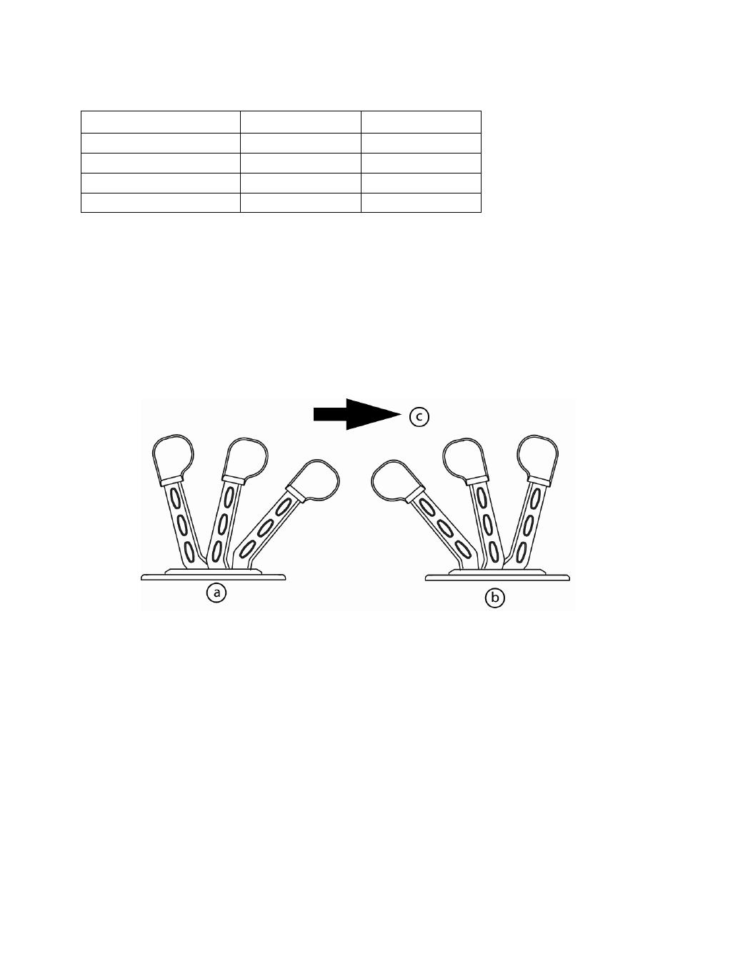
Important: Canting refers to the direction of bend in handle. Install the Livorsi DTS
Controls in the orientation specified for that model (aft-cant port, forward-cant port,
aft-cant starboard, or forward-cant starboard)
Cutting the Control Console Opening
1. Remove the Console Cutout page, located at the end of this document.
Important:
Hole patterns between the DTS flat base and DTS contour base
differ.
2. Transfer all drill holes and cut lines to the console in a suitable location. Refer to
Dimensions and Clearances for help determining the installation location.
Important: Ensure that the area below the console is clear of any wiring or items that
may hinder or be damaged by drilling/cutting.
a- Forward cant models
b- Aft cant models
c- Arrow pointing to the ship’s bow