LINK Systems OmniLink 5000 User Manual
Page 24
April 12, 2012
Manual Version 1.1
4.2
Stroke
Mode
Single Stroke
Drive
Speed
Stroke
Speed
SPM
SPM
0
0
Order
Counter
PC STATUS
Counter OFF
Auto
Sets
EXIT
0
0
Program/Run Switch
TOP
CHANGE
NAME
Air System Configuration
Transducer Type: Type 4: 200psi, 4-20ma
Tolerance: 2 psi
Fault Time: 30 seconds
Display Weight As: lbs
Min. Die Weight: 0 lbs
Max. Die Weight: 1000 lbs
Minimum Pressure: 5 psi
Maximum Pressure: 90 psi
Mode: ON
Name: Counter-Balance #1
Air Pressure: 56 psi
Hardware Detected: Fill/Dump
Air Slot: AS1
NEXT AIR
SLOT
Help
CHANGE
MODE
CHANGE
MAX PRES
CHANGE
UNIT
CHANGE
MIN FORCE
CHANGE
MAX FORCE
CHANGE
TIME
CHANGE
MIN PRES
CHANGE
TOLERANCE
CHANGE
TIME
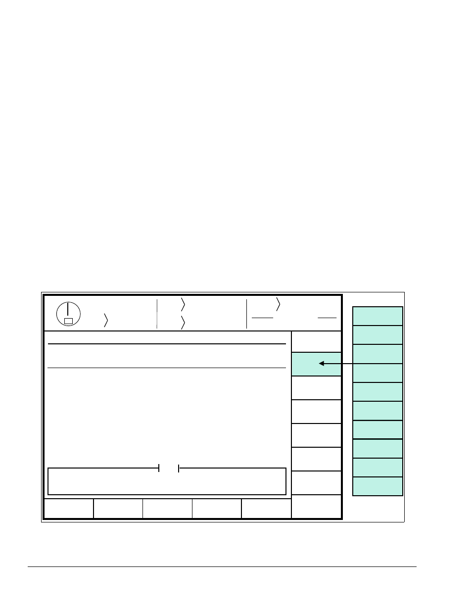
Figure 4.2: Example Air Configuration Screen
Section 4.2 Configuring the Auto-Setup board
The ASM must be configured for the each shut height and pressure module that is installed on it. The
configuration necessary depends on the particular kind of module.
Section 4.2.1 Configuring Counterbalance, Cushion, and Hydraulic Overload Modules
Counterbalances and cushions are conceptually very similar and use essentially the same control
techniques. Hydraulic overloads are somewhat different but are usually air controlled systems (there are
some non-air controlled hydraulic overloads but the auto-setup board does not support them at this
time). To get to the configuration screen for cushion, counterbalance, and hydraulic overload modules:
a) Go to the “Auto Sets” screen. This screen is reached by pressing the “AUTO SETS” softkey in
the Main Menu or Press Control screen.
b) With the RUN/PROG key switch in the PROG position, press the “CONFIGURE” softkey and
enter the configuration code. Note that the code is provided separately from this manual for
administrative control.
c) Press the “CONFIGURE AIR” softkey.
At this point the screen should look similar to Figure 4.2.
There are several parameters that must be configured in this screen. The editing cursor indicates which