Lingenfelter L460105297 Lingenfelter LNC-003 Dual RPM Launch Controller v2.7 User Manual
Page 7
Page 6 of 17
Nitrous, line-lock, trans-brake and other solenoid usage warning:
LPE has found that these solenoids can cause fly-back voltage levels at times in excess of 600 volts.
These voltage levels have the potential to damage sensitive electronics including the LNC-003, the
PCM/ECM and other modules in the vehicle. Lingenfelter Performance Engineering has developed
a transient voltage suppression (TVS) diode kit (PN L450080000) for use with line-lock solenoids,
trans-brake solenoids and other aftermarket automotive solenoids of this type. LPE recommends the use
of our noise suppression diode on all vehicles that have a line lock or trans-brake. This kit comes with
one TVS diode. If you have a vehicle with multiple solenoids we recommend obtaining additional TVS
diodes for those solenoids.
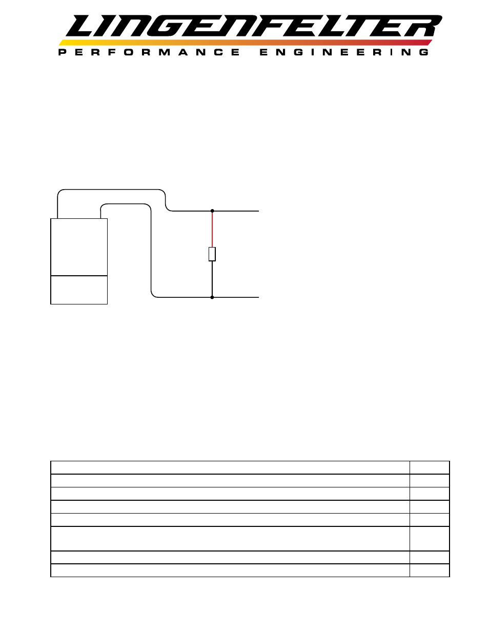
Solenoid
Install the TVS diode across the solenoid wires
as close to the solenoid as possible. Polarity does
not matter (Red and Black wires can go to either
solenoid wire). If there is no accessible ground
terminal to connect the diode to, such as the case
with a trans-brake solenoid, the diode should be
connected to the nearest ground source. In the
case of the diode for the trans-brake solenoid, the
diode should be connected to the transmission
case as it will provide a ground path.
LPE recommends using TVS diodes on:
• Nitrous solenoids
• Nitrous purge solenoids
• Fuel solenoids
• Line-lock solenoids
• Trans-brake solenoids
Example wiring diagrams:
The following pages show examples of how the LNC-003 can be wired in different vehicle applications.
Many other possible installation methods exist.
1998-2002 F-Body and 1997-2008 Corvette Factory Clutch Switch Diagram
page 7
Manual Transmission with Linelock
page 8
Manual Transmission with Linelock and Nitrous
page 9
Automatic Transmission with Linelock
page 10
Automatic Transmission with Linelock and Nitrous
page 11
1998-2002 F-Body and 1997-2008 Corvette Factory Clutch Switch Diagram with the
STOV-002 and LNC-003 modules
page 12
LNC-003 Recieving +12V Activation Input from NCC-001 or NCC-002 based on VSS
page 13
LNC-003 Wiring Diagram
page 14
TVS diode