Lingenfelter L460105297 Lingenfelter LNC-003 Dual RPM Launch Controller v2.7 User Manual
Page 5
Page 4 of 17
Installation:
• Make sure the ignition is off before beginning
installation.
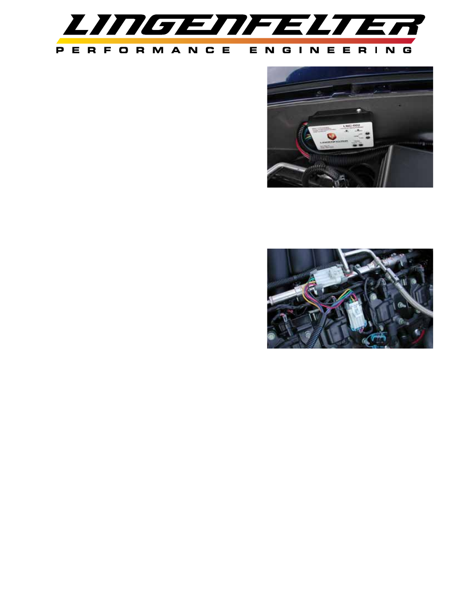
• You can mount the LNC-003 using the supplied hook
and loop tape or the supplied self tapping screws.
• Do NOT mount the LNC-003 directly on top of the
engine or near the exhaust manifolds due to heat
concerns.
• Do NOT mount the LNC-003 in the line of site
of high temperature objects such as exhaust
manifolds, turbine housings etc. If needed, put a
heat shield in between the heat source and the module to protect the plastic case.
• Do NOT install within 6” of nitrous solenoids or other devices with strong magnetic fields.
• If you have relocated coil packs, do not run the high voltage spark plug wires alongside the low
voltage coil pack wires. Keep the wires as far apart as possible and, if they do have to intersect,
have them intersect at right angles.
• Disconnect the pack connectors on each side of the
engine and then plug the LNC-003 wiring harnesses in
between on each side. It does not matter which bank of
cylinders each side of the LNC-003 harness connects
to.
• The only wiring that is required is for the trigger
wire(s) depending on how you want to enable the
device. See pages 7 to 13 for an example vehicle
wiring diagrams.
• The possible Primary RPM trigger/activation
connection methods are:
• Ground activation wire (green) - connect this wire to a source that supplies a ground path when
you want the LNC-003 to become active
• +12 volt activation wire (yellow) - connect this wire to a source that supplies +12 volts when
you want the LNC-003 to become active (i.e. brake light switch, line-lock solenoid)
• Switch connected in between the ground activation wire and the +12 volt activation wire (green
wire connected to yellow wire through a switch, usually a momentary switch)
• Ground activation wire connected to +12 volt activation wire (green connected to yellow) for
standard RPM limiter operation (LNC-003 always active)
• Set the desired Primary RPM switch activation point using the two ten position rotary switches for
the 1000 RPM increment (x1000) and the 100 RPM increment (x100).
• The Secondary RPM trigger/activation connection method is:
• +12 volt activation wire (orange) - connect this wire to a source that supplies +12 volts when
you want the Secondary RPM limit of the LNC-003 to become active (i.e. brake light switch,
line-lock solenoid)
• Set the desired Secondary RPM switch activation point using the two (2) sixteen position switches
for selecting hundreds of RPM (x100) and thousands of RPM (x1000) for the Secondary RPM limit
setting. Switch positions after 9 are not used.