Labconco Guardian 500 Airflow Monitor User Manual
Page 4
Labconco Instruction Sheet 3909501, Rev. B, ECO F597 4 of 6
Calibration Procedure
Each alarm module and enclosure/fume hood is unique and needs to be individually calibrated in
the field. The procedure for the adjustment is as follows:
1. Double check the installation to make sure that monitor and power supply are properly
installed.
2. Allow 10 minutes for the monitor to warm up once power has been connected.
3. Determine the low flow set point for your monitor. This is the value where the monitor
will first indicate a low flow condition. The red light will be on for this value. Refer to
your industrial hygiene officer for the proper low flow set point or consult the table
below.
4. Adjust your enclosure/fume hood airflow to the low flow set point as previously
determined. The exhaust flow can be lowered by adjusting the speed control on the
FilterMate or by using an adjustable damper on the exhaust blower. Typical alarm
conditions are set at face velocities of 10 to 20 feet per minute below the normal
operating conditions due to supply air and exhaust air fluctuations, as well as room air
cross drafts. See note 8 if the low airflow volume or sash opening cannot be adjusted.
5. Using a properly calibrated thermoanemometer, determine the velocity through the face
of the enclosure by taking a detailed velocity traverse. Divide the face area into equal
increments. One reading per square foot of face area is normally recommended for an
accurate traverse. Compute the average velocity for this area.
6. If the red light alarm is on, slowly turn the adjustment screw counterclockwise until the
green light is activated. If the green light is on, slowly turn the adjustment screw
clockwise until the red light comes on. Slowly turn the adjustment screw back until the
red light is activated. It is important that these adjustments be done in small increments,
at intervals about 30 seconds apart to allow for delayed reaction of the alarm itself. The
alarm low flow set point should now be set and the red light activated.
7. Readjust the enclosure airflow to its normal operating levels. The green light should now
be activated. Calibration is now complete.
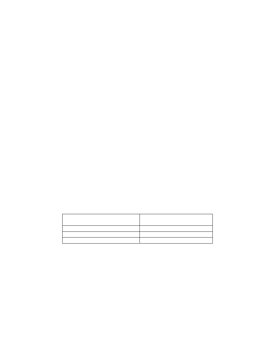
Enclosure Operating In Flow
Speed
Alarm Condition Set Point
Speed
100 fpm
80 - 90 fpm
80 fpm
60 - 70 fpm
60 fpm
40 - 50 fpm
8. Note: If the low airflow volume or sash opening cannot be adjusted, then a 1/4 to 1/3 of a
turn counterclockwise can be adjusted to set the airflow alarm condition at 10-25% below
normal operating levels.
Guardian 500 Alarm Activation
The audio and visual alarm will activate approximately 10-30 seconds after an alarm condition is
detected. To temporarily mute the audible alarm, press and release the test/reset button.
NOTE: After an alarm condition has been detected, the red light will stay on. The audible
alarm will remain muted until airflow returns to normal levels.