Labconco Guardian 1000 Digital Airflow Monitor User Manual
Page 5
Labconco Instruction Sheet 3909400, Rev. F, ECO F288 5 of 7
Digital 1000 Alternate Calibration Procedure - Constant Volume Conditions
1. To successfully calibrate, it will be necessary to change the face velocity by opening and
closing the enclosure’s sash. The airflow monitor is factory set to be calibrated with a
difference of at least 50 fpm and can be changed by adjusting the “lower/higher air
sample difference”. The in flow face velocity speeds provided in the chart below are
suggested to successfully calibrate the Digital 1000.
2. Before proceeding with calibration, it will first be necessary to configure the airflow
monitor. Go to the setup and then CAL CONFIG MENU and adjust the “lower/higher air
sample difference” to 10 fpm. This will allow you to successfully calibrate with
minimum difference values of 10 fpm.
3. While in CAL CONFIG MENU, change the “sensor difference” from 10% to 3%.
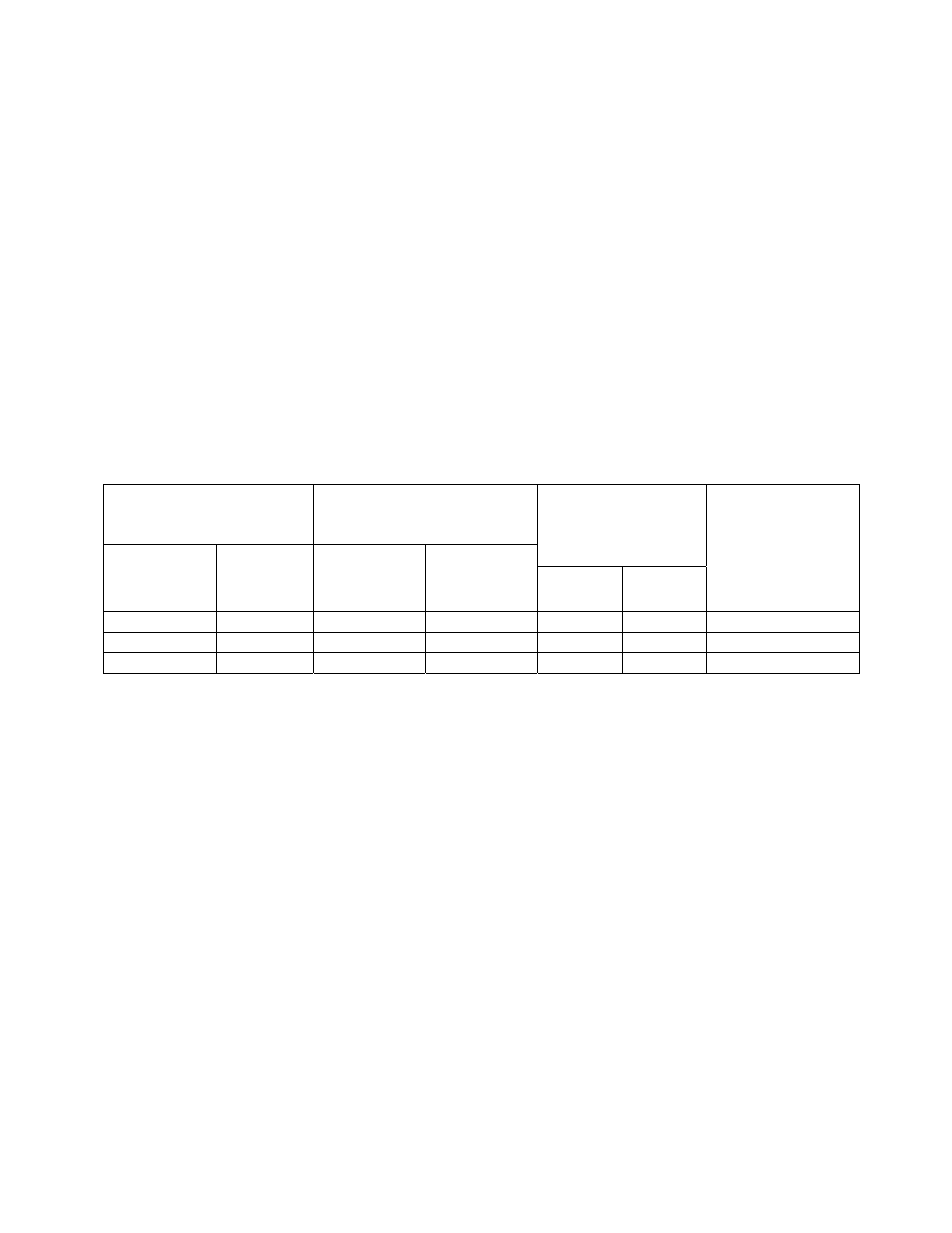
4. While in CAL CONFIG MENU, adjust the red low alarm to the desired setting (See the
chart below for range and suggested settings). Then adjust the yellow “CAUTION or
WARNING” to the desired setting (See the chart below for range and suggested settings).
Then adjust the “CAUTION or WARNING” air reset to 3 fpm. This sets the alarm
condition.
CAUTION WARNING
“YELLOW LED” Setting
LOW ALARM
“RED LED”
Setting
Low Calibration
Set Point
Sash Open
(fpm)
Range
user defined
(fpm)
Suggested
Set Point
(fpm)
Range
user defined
(fpm)
* Suggested
Set Point
(fpm)
8” Sash
Height
10” Sash
Height
High Calibration
Set Point
or Enclosure
Operating
Inflow Speed
Sash Closed
43 – 53
51
40 – 50
48
27
23
60 fpm
63 – 73
67
60 – 70
64
37
30
80 fpm
83 - 93
83
80 - 90
80
47
37
100 fpm
*
Because of airflow fluctuations in a typical laboratory environment Labconco suggests setting
the “RED LED” low alarm set point to 20% below the enclosure’s operating speed.
5. To complete the CAL CONFIGURATION, be sure to enter “DONE”. If needed, refer to
the Configuration procedure provided on the following page for additional details.
6. To start the calibration mode, enter “CALIBRATION” mode on the display from the
SETUP menu.
7. Follow the instructions on the display and simulate the low exhaust volume by fully
opening the sash. You may measure the average face velocity for the low calibration set
point or utilize the calculated value provided in the chart above. The average face
velocity for the low set point is accurately measured by dividing the opening of the
enclosure into equal area grids consisting of at least 9 data collection points and
measuring the velocity at the center of each grid with a calibrated thermo anemometer.
Enter the low value on the display. Be careful not to block the opening. The low exhaust
volume calibration will take about 5 seconds.
8. Now simulate the high exhaust volume by fully closing the sash to its normal operating
position. Measure the average face velocity for the high calibration set point to confirm
that the source of constant air volume is providing the desired face velocity for the
enclosure. The average face velocity for the high set point is accurately measured by
dividing the opening of the enclosure into equal area grids consisting of at least 3 data
collection points and measuring the velocity at the center of each grid with a calibrated