LA Audio MS1224 User Manual
Page 9
Page 9
5.0 EXTERNAL CONNECTIONS
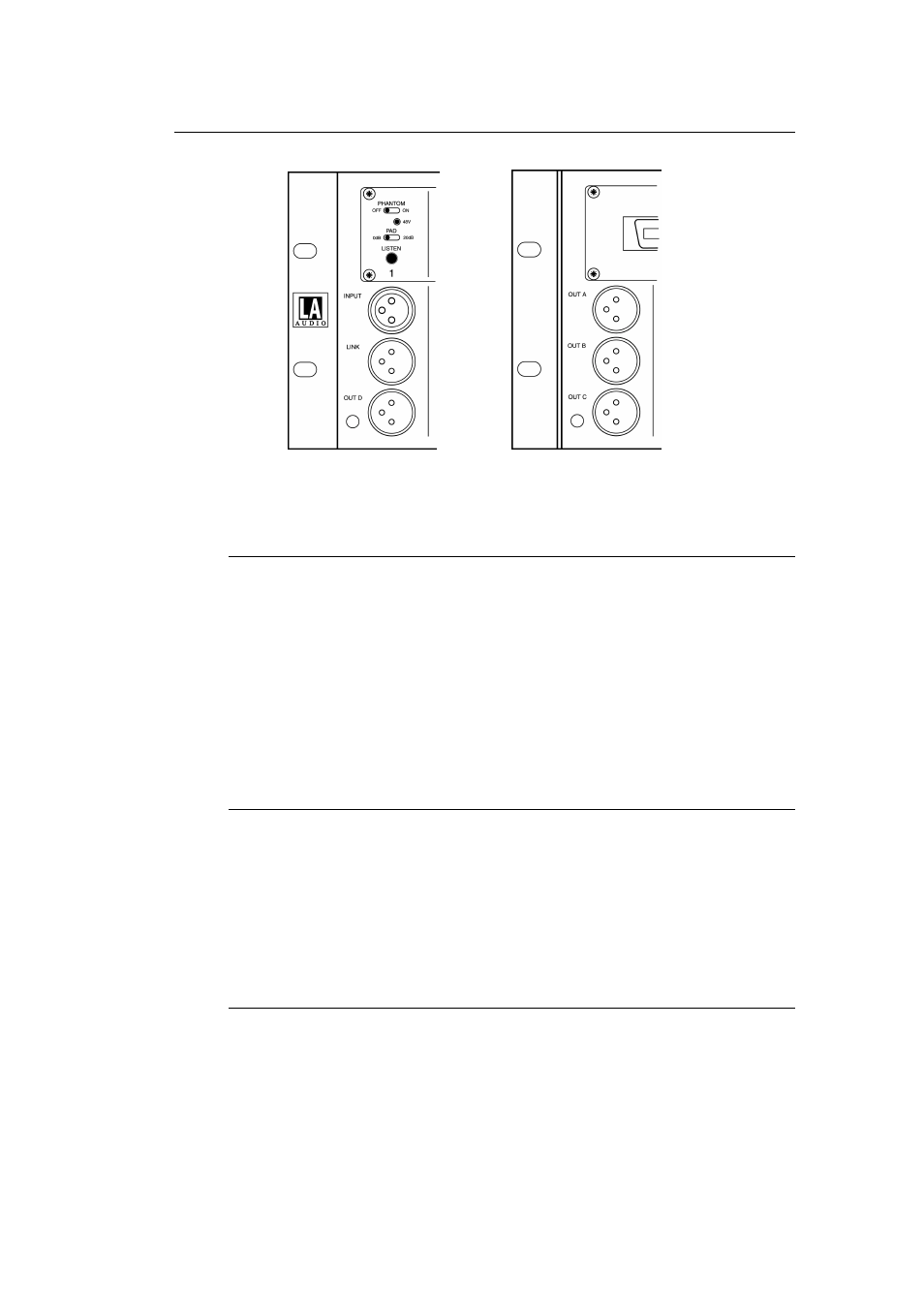
Option A - Front view
Option A - Rear view
5.1 INPUT
The Microphone input is electronically balanced via a XLR-F connector with pin 2
wired hot (signal +). Input impedance is 2k and is suitable for low impedance
dynamic or capacitor microphones.
Although the inputs are designed for balanced operation either pin 2 or pin 3 can
be connected via the external cable to pin 1 for unbalanced operation.
Pin 1 on the Microphone XLR is grounded via the INPUTS Ground Lift switch on
the power supply - see Section 6.1.
5.2 LINK
LINK is wired in parallel with the INPUT connector and can be used to provide a
direct feed from the source.
Ex-works the LINK connector is fitted on the front of unit (Option A). It can
however be swapped for OUTPUT A which is normally mounted on the rear
panel (Option C) - see Section 5.6.
5.3
OUTPUT A, B, C and D
All outputs on the MS1224 are transformer balanced on 2 pin XLR-M connectors
with pin 2 wired hot (signal +).
Either pin 2 or pin 3 can be connected to pin 1 via the external cable to provide
an unbalanced feed.
Pin 1 on OUTPUT A, B and C are connected to ground via the associated
Ground Lift switches on the Power Supply unit - see Section 6.1.