LA Audio MS1224 User Manual
Page 13
Page 13
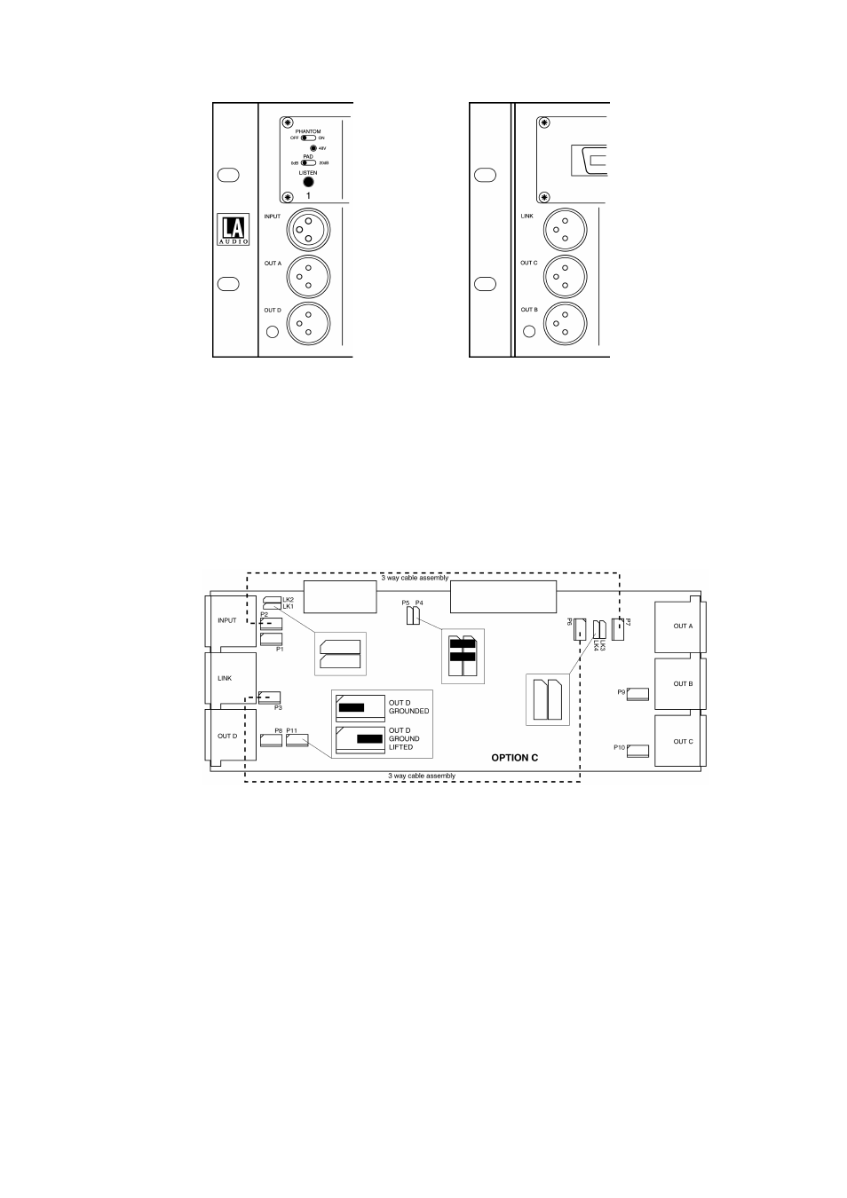
Option C - front view
Option C - rear view
•
Referring to the Channel board diagram –
•
Remove the 3 x jumper links fitted to LK1 and LK2
•
Remove the 3 x jumper links fitted to LK3 and LK4
Channel board link positions for Option C and D
•
Fit a 3 way, 16cm cable assembly (Order No. 2010205) between P3 & P6
•
Fit a 3 way, 16cm cable assembly (Order No. 2010205) between P2 & P7
•
Turn chassis through 180° (only required for Option D) i.e. 10 way ribbon
cable connectors (J4) on channel boards are now closer to the rear of the
unit, refit the main assembly – 8 x M3 Hex, Button head screws (2mm Allen
Key required).
•
Re-fit Switch panel assembly – 8 x M3 Pan screws and plug in 12 x Ribbon
cable connectors.
•
Re-fit Connector panel assembly – 8 x M3 Pan screws and plug in the 20
way ribbon cable.