LA Audio MS1224 User Manual
Page 12
Page 12
Coverting from option A to Option B:
•
Remove the top cover – 8 x M3 countersunk screws.
•
Remove chassis – 8 x Hex Button screws (2mm AF Allen Key required) and
4 x M3 x 6 countersunk screws on base.
•
Disconnect the 10 way ribbon cable connector from each of the channel
boards (J4).
•
Disconnect the 4 way power cable from the rear of the Centronics connector
panel.
•
Disconnect 20 way ribbon cable from Centronics panel.
•
Remove the Switch panel assembly – 8 x M3 Pan screws.
•
Remove the Connector panel assembly – 8 x M3 Pan screws.
•
Turn chassis through 180° i.e. 10 way ribbon cable connectors (J4) on
channel boards are now closer to the rear of the unit, refit the main assembly
to the chassis – 8 x M3 Hex, Button head screws (2mm Allen Key required)
and 4 x M3 x 6 countersunk screws on base.
•
Re-fit Switch panel assembly to front of unit – 8 x M3 Pan screws and plug in
12 x Ribbon cable connectors.
•
Re-fit Connector panel assembly to rear of unit – 8 x M3 Pan screws and
plug in the 20 way ribbon cable.
•
Re-connect 4 way power cable to rear of Switch panel.
•
Re-fit cover – 8 x M3 countersunk screws.
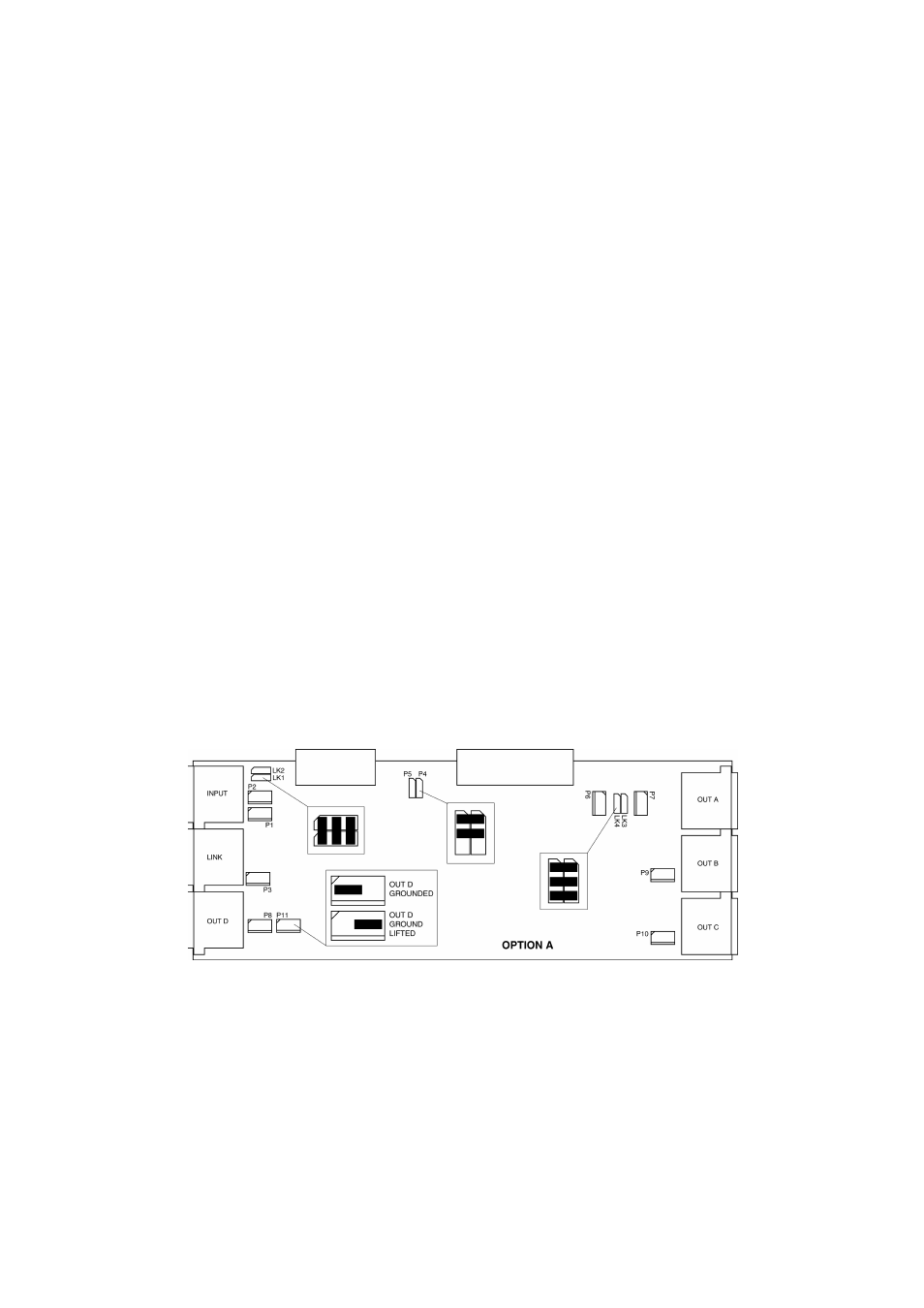
Channel board link positions for Option A and B
Converting from Option A to Option C:
Follow the above procedure but before re-assembling make the following
changes to the Channel boards -