LA Audio MS1224 User Manual
Page 10
Page 10
Pin 1 on OUTPUT D is normally supplied with pin 1 ground lifted. Refer to Section
5.9 for details of how to ground OUTPUT D.
5.4 POWER
IN
A 36 way Centronics style connector carries all DC power, signal monitoring and
grounding connections.
Normally connected to the MS1224 Power Supply Unit - see Section 6.0.
5.5 POWER
OUT
A duplicate power connector to allow easy daisy chaining of multiple MS1224
Active Mic Splitters to a common power supply.
5.6 SIGNAL
LEVELS
The Input to Output gain on the MS1224 is 0dB i.e. unity. Maximum input signal
level will depend on the setting of the PAD switch.
The 0dB position (switch up) is for microphone levels and maximum input level is
0dBu i.e. 0.775Vrms. The -20dB position should be used for line level signals.
Maximum input level is then +20dBu and overall voltage gain will be -20dB.
Maximum Output level from the MS1224 is +20dBu into a 600R load.
5.7
MULTIWAY CONNECTOR OPTION
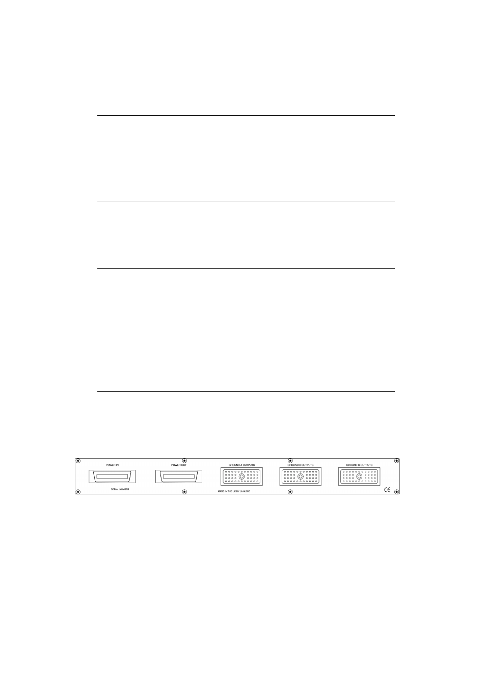
In the standard ex-works configuration the connector panel on the MS1224 Active
Mic Splitter has no provision for multiway connectors. However an optional
connector panel is available with cut outs for up to three 56way EDAC style
connectors - see following diagram.
Connections to the multicore connectors depend on which option is used. The
following is a list of available connectors on each of the channel cards -
Option A and B:
Option C and D:
INPUT
P1
INPUT
P1
OUT
A
P7
OUT
A
LK4
OUT
B
P9
OUT
B
P9
OUT
C
P10
OUT
C
P10
OUT
D
P8
OUT
D
P8
LINK
P3
LINK
LK2