Internal modem wiring, Internal modem, With “call out upon alarm”) – Heath Consultants Heath Data Recorder (HDR) User Manual
Page 10
10
Internal Modem
The HDR may be equipped with an internal modem and phone line surge suppressor. The modem is pre-configured and
pre-wired from the factory, ready for remote communication. If the HDR is equipped with the phone line suppressor, it
will be connected directly into the modem’s RJ-11 connector. A 12-volt battery pack (8 “AA” batteries) is supplied, but
not connected when shipped. The user must connect prior to remote communication. Assuming one two-minute call per
day, every day, the battery should provide approximately 2 years of service.
To connect a phone line to the modem, insert the phone cable through the wire gland into the case (see Figure 1). The
cable must be terminated with a RJ-11 connector. Plug into surge protector if provided; else plug directly to the modem.
The optional phone line surge suppressor will sacrifice itself to protect the equipment in the event of a destructive power
surge on the phone line.
Caution:
Unit must be connected to proper ground to allow the surge suppressor to operate properly.
Caution
: Internal modem option is not currently certified for use in hazardous environments. An external modem should
be used when necessary. Refer to drawing MTM-308-1 for field wiring requirements on external power and modem
connections to maintain intrinsic safety.
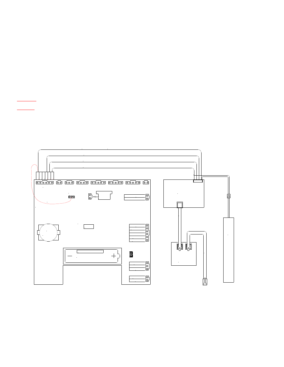
Internal Modem Wiring
(with “Call out upon Alarm”)
CTS
RT
S
CD
TXM
RX
M
GN
D
GND
INDEX B
STOBE
INDEX A
STOBE
3V SYS
GND
GAS TEMP 2
1.5VDC
GND
12VDC
GND
BUTTON
JP5
CR2032
3V
1 2 3
ASSY#: 77R65-9320
REV F
3.6V "AA" Lithium
OPEN
JP1*
DISPLAY
BACKUP BATTERY
WIRED TO
*Jumper wire
Yellow (CTS)
Red (GND)
Gray (RXM)
Blue (TXM)
Heath 2400
Baud Modem
(Wake-up wire for "Call Out Upon Alarm")
12V
Modem
Bat
ter
y
(Wake-up wire for "Call Out Upon Alarm")
J13
P
h
o
n
e
Line
P
h
o
n
e
Line
Surge
Protector
(Optional)
Connect the RX, TX, GND & CTS wires from the HDR to the modem using the modem harness required (contact
Heath Consultants Inc for this harness). Plug in the jumper wire to JP5.
Note 1:
For “Call out upon alarm” feature. The modem harness connects Pin 2 of JP5 to Pin 6 of J13 (Modems
that stay online 100% doesn’t require this jumper).
Note 2: If the “Analog Modem” is NOT selected, the calls will be dialed 2 minutes apart. However, if the “Analog
Modem” is checked, the calls will be completed ASAP (Approximately 20 seconds).
Note 3: A “Manual” alarm must be reset in order to get a second “Call out” alert. An “Auto” alarm will call out
multiple times if the trip points are exceeded in succession.