Physical connections 25, Module expansion matrix, 1 x expansion area for optional modules – Hatteland Display HT 221 (2U Size) User Manual
Page 25
Physical Connections
25
IND100133-55
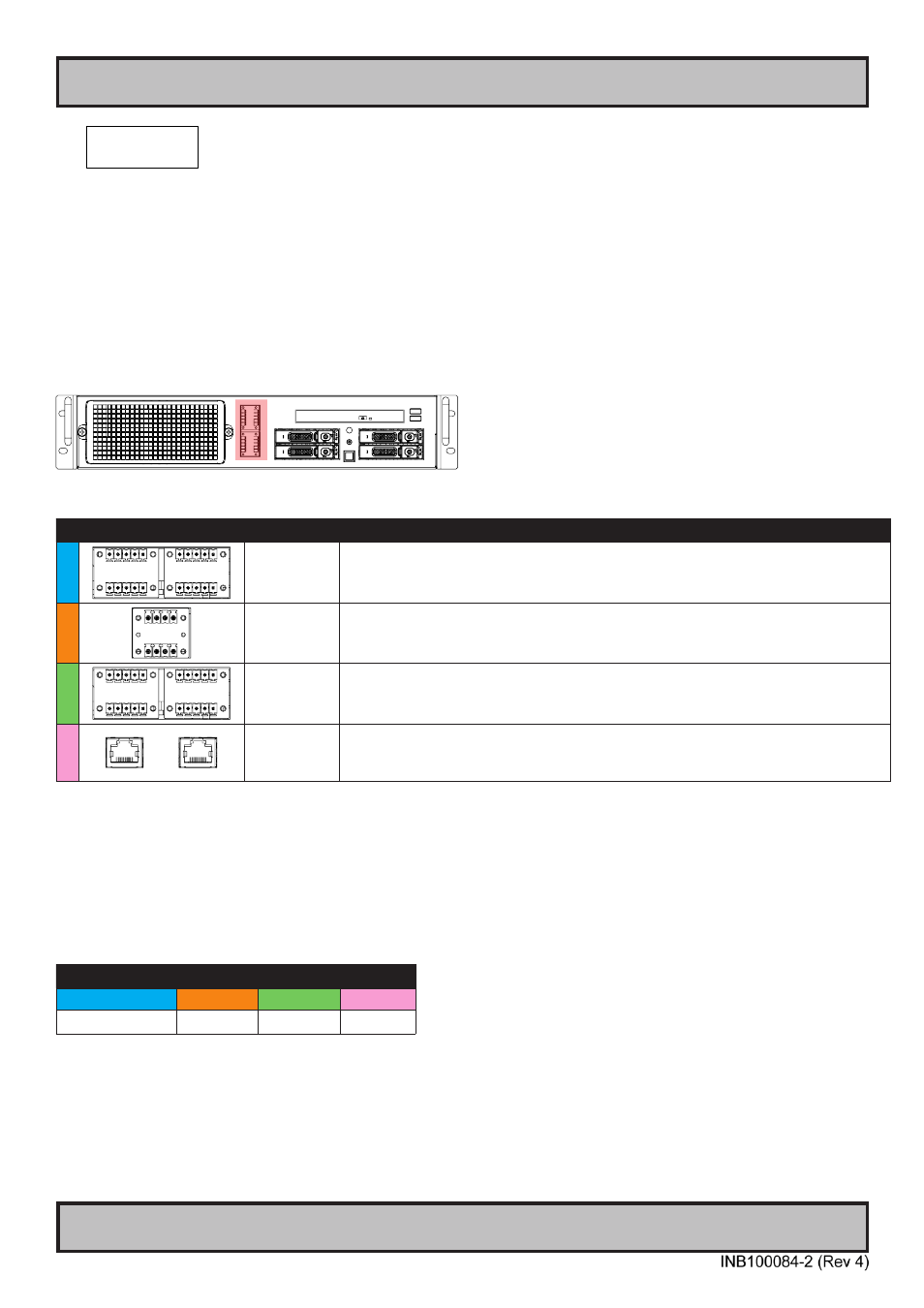
1 x EXPANSION AREA for Optional modules:
The HT 221 computers supports a multitude of combinations and gives additional features to the unit by taking
advantage of the expansion area in front. The table below lists all modules currently available for factory mounting.
Most of the modules connects internally through USB allowing for easy driver installation and usage, others connects
directly to the internal motherboard.
For detailed pinout assignments and connector information, please review “Pinout Assignments” and “Housing /
Terminal Block Connector Overview” in this manual. Each option have their own dedicated bracket to house the
Optional Module securely to the unit’s outer chassis. For technical specifications, see separate datasheets in this
manual for each factory mounted module.
Example illustration showing 1 module installed (DIO):
Available Modules (review dedicated Datasheets in this manual):
# Illustration Module
Code ID
Description / Function
B
NMEA COM
RS-422/RS-485 NMEA Isolated / ECDIS Module
4 x 5-pin Terminal Block 3.81 connection
Typenumber: PCA100293-1
C
CAN
CAN isolated, 2 channel Module
Connector: 4-pin Terminal Block 3.81 connection
Typenumber: HT 00254 OPT-A1
D
DIO
Digital IO Isolated, 4 Output + 4 Input Module
Connectors: 4 x 5-pin Terminal Block 3.81 connection
Typenumber: HT 00268 OPT-A1
E
LAN
LAN 10/100Mbps, 2 ports Module
Connectors: RJ45
Typenumber: PCA100298-1
Module Expansion Matrix
Table below indicates how many duplicates of the same module can be installed at the same time. Due to limited
number of internal connectors, different upper/lower area size and technical limitations some combinations (with
duplicates) are naturally not possible to achieve.
Colored Table Cell refers to the “Upper Row” and “Lower Row” tables above from previous page.
NMEA COM
CAN
DIO
LAN
B
C
D
E
1
(3)
*
1
1
1
* pending