Analog output – Hanna Instruments HI 23 User Manual
Page 16
31
30
The type (voltage or current) and the range of the output
analog signal is selectable through the jumpers on the board.
Analog output options are as follows:
0-5 VDC; 1-5 VDC
0-10 VDC (default)
0-20 mA; 4-20 mA (default)
0-1 mA
Choice between different ranges with the same configura-
tion (for example 0-20 mA and 4-20 mA) is achieved via
software by entering the setup mode and selecting code 40
(see Setup Mode section for exact procedure).
Factory default is 0-20 mA, 4-20 mA for the current output
and 0-10 VDC for the voltage output.
In any case, contact the nearest Hanna Customer Service
Center for changing of the default configuration.
By default the minimum and maximum values of analog
output correspond to the minimum and maximum of the
selected range of the meter. For example, for a controller with
a selected 0 to 1999 µS range and analog output of 4-20
mA, the default values are 0 and 1999 µS corresponding to
4 and 20 mA, respectively.
These values can be changed by the user to have the analog
output matching a different EC or TDS range, for example,
4 mA = 30 mS and 20 mA = 50 mS.
To change the default values, the setup mode must be en-
tered. Setup codes for changing the analog output minimum
and maximum are 41 or 42, respectively. For the exact pro-
cedure, refer to the setup mode section in the manual.
Note
The analog output is factory calibrated through software. The
user may also perform the calibration procedure as explained
in the following. It is recommended to perform the output
calibration at least once a year.
Note
Analog output resolution is 1.5‰ f.s. with 0.5% f.s. accu-
racy.
Note
The analog output is “frozen” when entering the setup or
calibration mode (after password confirmation).
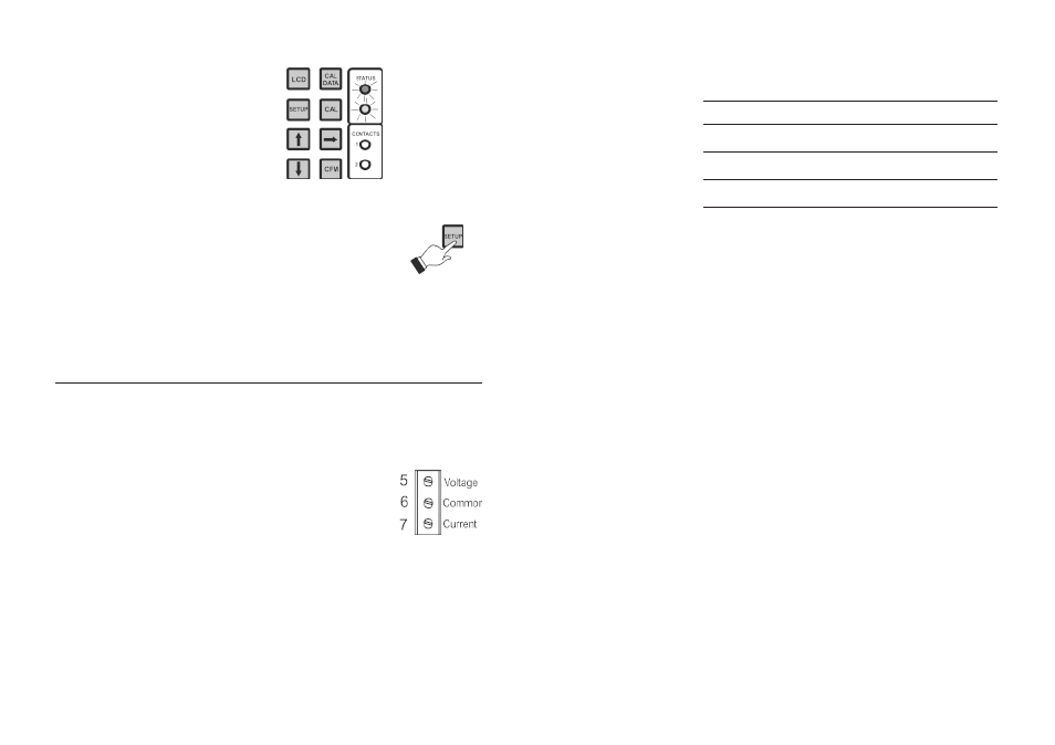
Control actions are stopped as soon as the
user presses SETUP and enters the pass-
word.
In order to reactivate the control mode, use
code 02 of setup (see “Setup” section). Oth-
erwise, the meter remains in idle mode.
ANALOG OUTPUT
Models HI 23xy1 and HI 24xy1 are provided with the ana-
log output feature.
The output is galvanic separated and can be a voltage or a
current.
Pin 5 is the voltage output, pin 6 is the
analog output common and pin 7 is the
current output.
With the recorder, simply connect the
common port to the common output
and the second port to the current out-
put or voltage output (depending on
which parameter is being used) as de-
picted aside.