Hanna Instruments mV 600 Series User Manual
Page 17
33
32
mV INPUT CALIBRATION
The pH/mV controller is factory calibrated for the mV and
temperature inputs. However, the user may also perform a
mV calibration.
• Short the Connection for Potential Matching Pin (#9 at
page7) and the Connection for the Electrode Reference
(#8 at page 7) with a jumper wire.
• Attach a HI 931001 (pH 500) or HI 8427 (mV 600) simu-
lator to the BNC socket.
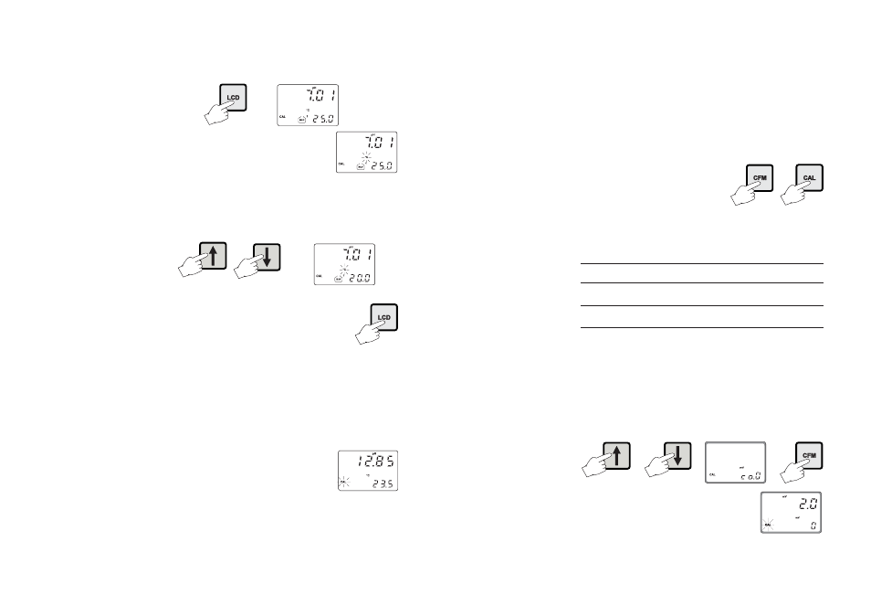
• Press and hold first CFM and then
CAL to enter the mV Input Cali-
bration mode.
• Execute the password procedure.
• With pH 500, the meter will ask for the calibration proce-
dure code number. The following table lists the possible
values of the input code and calibration points:
INPUT
CODE
POINTS
CAL.VALUES
INPUT RANGE
mV
0
2
0 & 350 or 0 & 1900*
±2000,
Temp.
1
2
0 & 25 or 0 & 50 -9.9 to 120.0
°
C
* One of the points must be 0. 1900 mV calibration point is available
on mV 600 models only.
When calibrating the mV of mV 600 models, enter the
calibration mode by pressing CAL and confirming the pass-
word (as for pH calibration of pH 500). No code selection
is required.
• Use or to select code 0 for mV calibration and press
CFM to enter.
• CAL will blink on the LCD until the
meter confirms a steady reading.
CALIBRATION WITH MANUAL TEMPERATURE COMPENSATION
• Enter the calibration procedure and press LCD to display
the temperature on the secondary LCD.
• Unplug any temperature probe that may
be attached to the meter. The "°C" sym-
bol will flash.
• Note the temperature of the buffer solutions with a
ChecktempC or an accurate thermometer with a resolution
of 0.1°C.
• Use or to manually adjust the display reading to the
value of the reference thermometer (e.g. 20°C).
• Follow the calibration procedure above (see page 27).
Note
To toggle between the pH buffer and the
temperature press LCD.
When a one-point calibration is carried out only the pH off-
set is computed and stored, while the pH slope is fixed
according to the theoretical values.
With a two-point calibration, offset and slope are computed
to fit the two calibration points. With a three-point calibra-
tion the offset and first slope values refers to pH 4.01 and
7.01 buffers, while the second slope refers to pH 7.01 and
10.01 buffers.
Note
If the process meter has never been cali-
brated or an EEPROM reset has occurred,
the meter continues to perform measure-
ment. However, user is informed of a pH calibration
requirement by a blinking “CAL” (see “Startup” section).
The device must be calibrated within the temperature range
of 0-95°C. Outside this range, the buffer pH values are not
reliable.